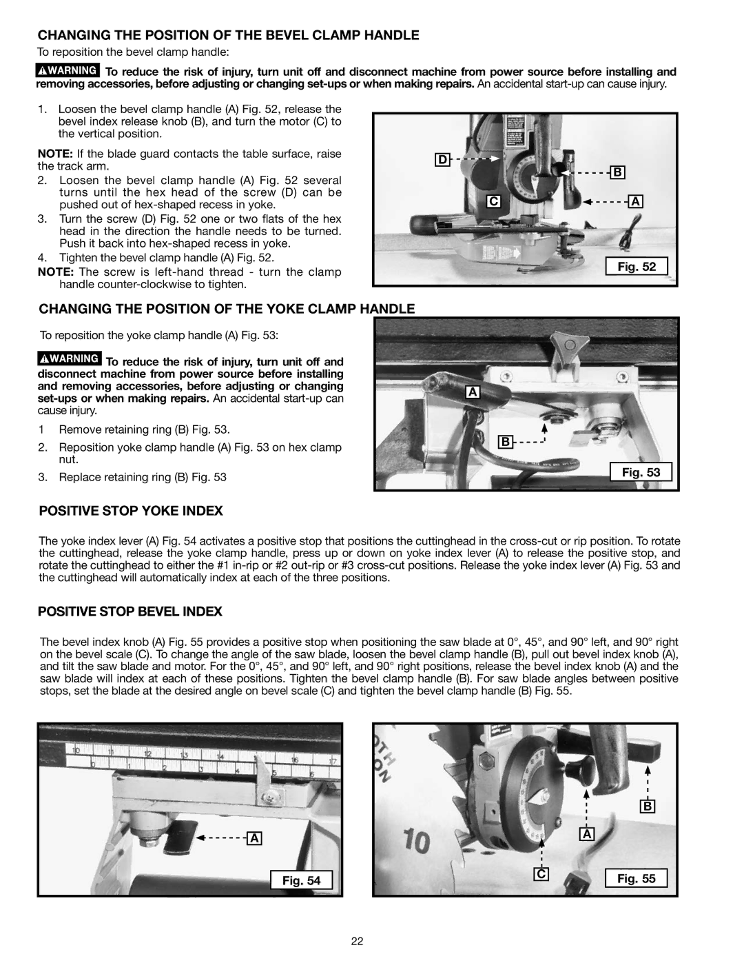
CHANGING THE POSITION OF THE BEVEL CLAMP HANDLE
To reposition the bevel clamp handle:
![]() To reduce the risk of injury, turn unit off and disconnect machine from power source before installing and removing accessories, before adjusting or changing
To reduce the risk of injury, turn unit off and disconnect machine from power source before installing and removing accessories, before adjusting or changing
1.Loosen the bevel clamp handle (A) Fig. 52, release the bevel index release knob (B), and turn the motor (C) to the vertical position.
NOTE: If the blade guard contacts the table surface, raise the track arm.
2.Loosen the bevel clamp handle (A) Fig. 52 several turns until the hex head of the screw (D) can be pushed out of
3.Turn the screw (D) Fig. 52 one or two flats of the hex head in the direction the handle needs to be turned. Push it back into
4.Tighten the bevel clamp handle (A) Fig. 52.
NOTE: The screw is
D
C
![]()
![]() B
B
![]()
![]() A
A
Fig. 52
CHANGING THE POSITION OF THE YOKE CLAMP HANDLE
To reposition the yoke clamp handle (A) Fig. 53:
![]() To reduce the risk of injury, turn unit off and disconnect machine from power source before installing and removing accessories, before adjusting or changing
To reduce the risk of injury, turn unit off and disconnect machine from power source before installing and removing accessories, before adjusting or changing
1 Remove retaining ring (B) Fig. 53.
2.Reposition yoke clamp handle (A) Fig. 53 on hex clamp nut.
3.Replace retaining ring (B) Fig. 53
a
b ![]()
![]()
Fig. 53
POSITIVE STOP YOKE INDEX
The yoke index lever (A) Fig. 54 activates a positive stop that positions the cuttinghead in the
POSITIVE STOP BEVEL INDEX
The bevel index knob (A) Fig. 55 provides a positive stop when positioning the saw blade at 0°, 45°, and 90° left, and 90° right on the bevel scale (C). To change the angle of the saw blade, loosen the bevel clamp handle (B), pull out bevel index knob (A), and tilt the saw blade and motor. For the 0°, 45°, and 90° left, and 90° right positions, release the bevel index knob (A) and the saw blade will index at each of these positions. Tighten the bevel clamp handle (B). For saw blade angles between positive stops, set the blade at the desired angle on bevel scale (C) and tighten the bevel clamp handle (B) Fig. 55.
![]()
![]() A
A
Fig. 54
C
b
A
Fig. 55
22