Operation
Adjusting the Anti-Scalp Rollers
It is recommended to change the
1.Stop the machine and move the motion control levers outward to the neutral locked position.
2.Disengage the PTO.
3.Engage the park brake.
4.Stop the engine, remove the key and wait for all moving parts to stop.
5.After adjusting the height of cut, adjust the
6.Place the rollers in one of the positions shown (Figure 17). Rollers will maintain 3/4 inch (19 mm) clearance to the ground to minimize gouging and roller wear or damage.
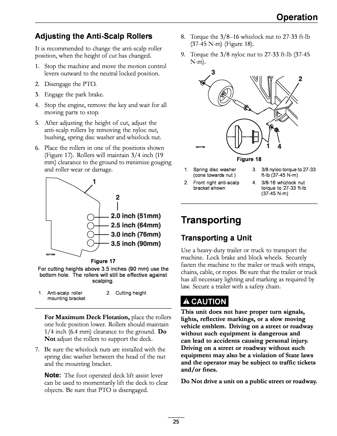
8.Torque the
9.Torque the 3/8 nyloc nut to
Figure 18
1. | Spring disc washer | 3. | 3/8 |
| (cone towards nut ) |
| |
2. | Front right | 4. | |
| bracket shown |
| torque to |
|
|
| |
|
|
|
|
Figure 17
For cutting heights above 3.5 inches (90 mm) use the bottom hole. The rollers will still be effective against scalping.
1. | 2. Cutting height |
mounting bracket |
|
For Maximum Deck Flotation, place the rollers one hole position lower. Rollers should maintain 1/4 inch (6.4 mm) clearance to the ground. Do Not adjust the rollers to support the deck.
7.Be sure the whizlock nuts are installed with the spring disc washer between the head of the nut and the mounting bracket.
Note: The foot operated deck lift assist lever can be used to momentarily lift the deck to clear objects. Be sure that PTO is disengaged.
Transporting
Transporting a Unit
Use a
![]()
![]() CAUTION
CAUTION
This unit does not have proper turn signals, lights, reflective markings, or a slow moving vehicle emblem. Driving on a street or roadway without such equipment is dangerous and can lead to accidents causing personal injury. Driving on a street or roadway without such equipment may also be a violation of State laws and the operator may be subject to traffic tickets and/or fines.
Do Not drive a unit on a public street or roadway.
25