5.1.22Wheel Hub – slotted nut torque specification
Service Interval: 500 hrs
When tightening the slotted nut on the wheel motor tapered shaft:
a)Torque the slotted nut to 125
5.1.23Fuel Tank – mounting hardware specification
When installing the nuts on the fuel tank studs, fully tighten the nyloc nut and back off ½ turn. This allows for normal fuel tank expansion and contraction with changes in temperature and fuel levels.
5.1.24Thread locking adhesives such as “Loctite 242” or
a)Pump drive sheave set screws.
b)Square head setscrews on Hydro pump control arms.
c)Sheave retaining bolt in the end of engine crankshaft, blower shaft and jackshaft.
d)Caster wheel spacer nuts
e)Fuel tank bulkhead fitting nuts.
5.1.25Dielectric grease is used on blade type electrical connections to prevent corrosion and loss of contact. Do not apply grease to sealed connectors inside hopper.
5.2 ADJUSTMENTS
IMPORTANT: Disengage PTO, shut off engine, wait for all moving parts to stop, and remove key before servicing, cleaning, or making any adjustments to the unit.
5.2.1Pump Drive Belt Tension.
Spring Tensioned - No adjustment necessary.
5.2.2PTO Belt Replacement.
a)Stop engine, wait for all moving parts to stop, and remove key.
b)With engine “off”, engage PTO lever, then remove the hairpin and clevis pin at the bottom of the PTO brake band.
c)Rotate the brake band upwards out of the way of the belts keeping clear of the belt drive.
d)Disengage PTO lever.
e)Remove current belts.
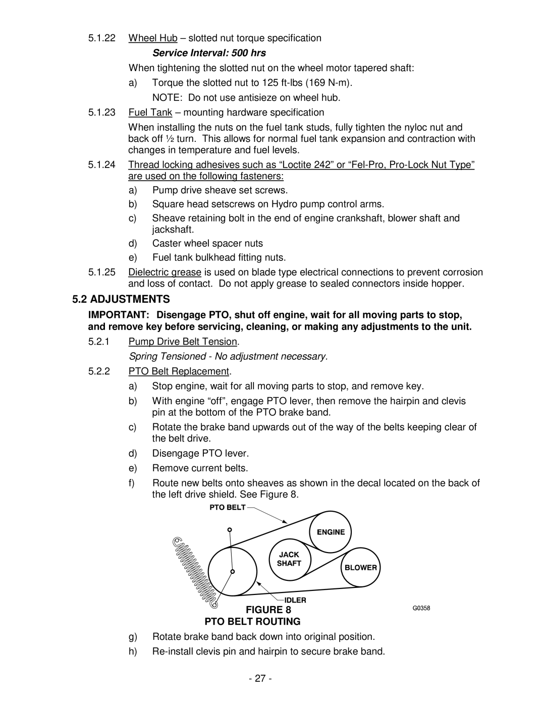
f)Route new belts onto sheaves as shown in the decal located on the back of the left drive shield. See Figure 8.
FIGURE 8
PTO BELT ROUTING
g)Rotate brake band back down into original position.
h)
-27 -