j)Tighten the 4 engine mounting bolts and 4 jackshaft mounting bolts. Check alignment after tightening.
k)
l)Swing fuel tank in and
m)Complete Pump Drive Pulley Alignment Section 5.2.13.
5.2.13Pump Drive Pulley Alignment
Pump drive pulley alignment is necessary for any of the following conditions:
•The engine mounting bolts have been loosened or the engine has been moved or replaced.
•The pump pulleys have been loosened, moved, or replaced.
•The PTO pulley alignment (Section 5.2.11) has been performed.
a)Stop engine, wait for all moving parts to stop, and remove key.
b)Loosen set screws on the both pump pulleys.
c)Using a straight edge, align each pump pulley with the engine pulley by sliding along the pump shaft. See Figure 19.
d)
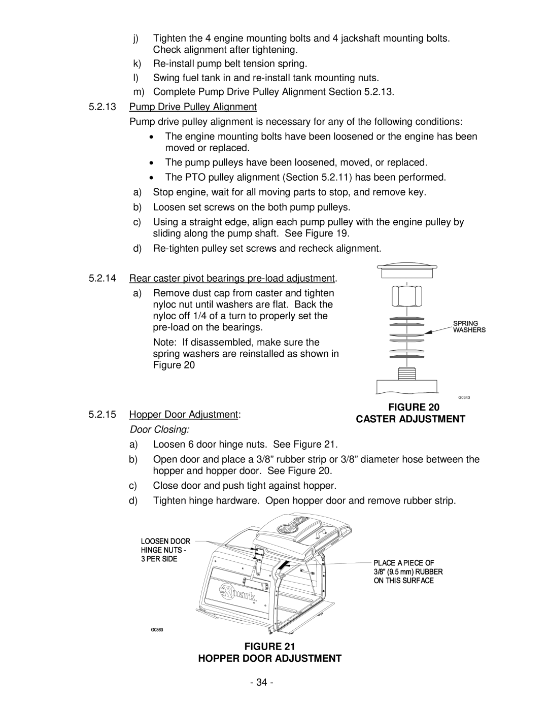
5.2.14Rear caster pivot bearings
a)Remove dust cap from caster and tighten
nyloc nut until washers are flat. Back the nyloc off 1/4 of a turn to properly set the
Note: If disassembled, make sure the spring washers are reinstalled as shown in Figure 20
5.2.15 Hopper Door Adjustment: | FIGURE 20 | |
CASTER ADJUSTMENT | ||
Door Closing: | ||
|
a)Loosen 6 door hinge nuts. See Figure 21.
b)Open door and place a 3/8” rubber strip or 3/8” diameter hose between the hopper and hopper door. See Figure 20.
c)Close door and push tight against hopper.
d)Tighten hinge hardware. Open hopper door and remove rubber strip.
FIGURE 21
HOPPER DOOR ADJUSTMENT
- 34 -