5.2.5Adjust Seat Switch
a)If necessary, adjust the seat actuator rod length to where the machine will shut off when the operator raises off the seat (with brake disengaged or PTO engaged) but will continue to run with operator in seat (a slight shift in weight should not shut machine off).
NOTE: To prevent the engine from cutting out when operating over rough ground, the unit is equipped with a
b)To adjust seat switch actuator rod length, loosen lock nut on bottom of the actuator rod (5/16 x 5 1/2” bolt) and adjust the nuts to move the actuator plate/washer up or down on the rod, then retighten.
5.2.6Brake Adjustment.
Check to make sure each brake is adjusted properly.
a)Pull the brake lever up and back to the engaged position.
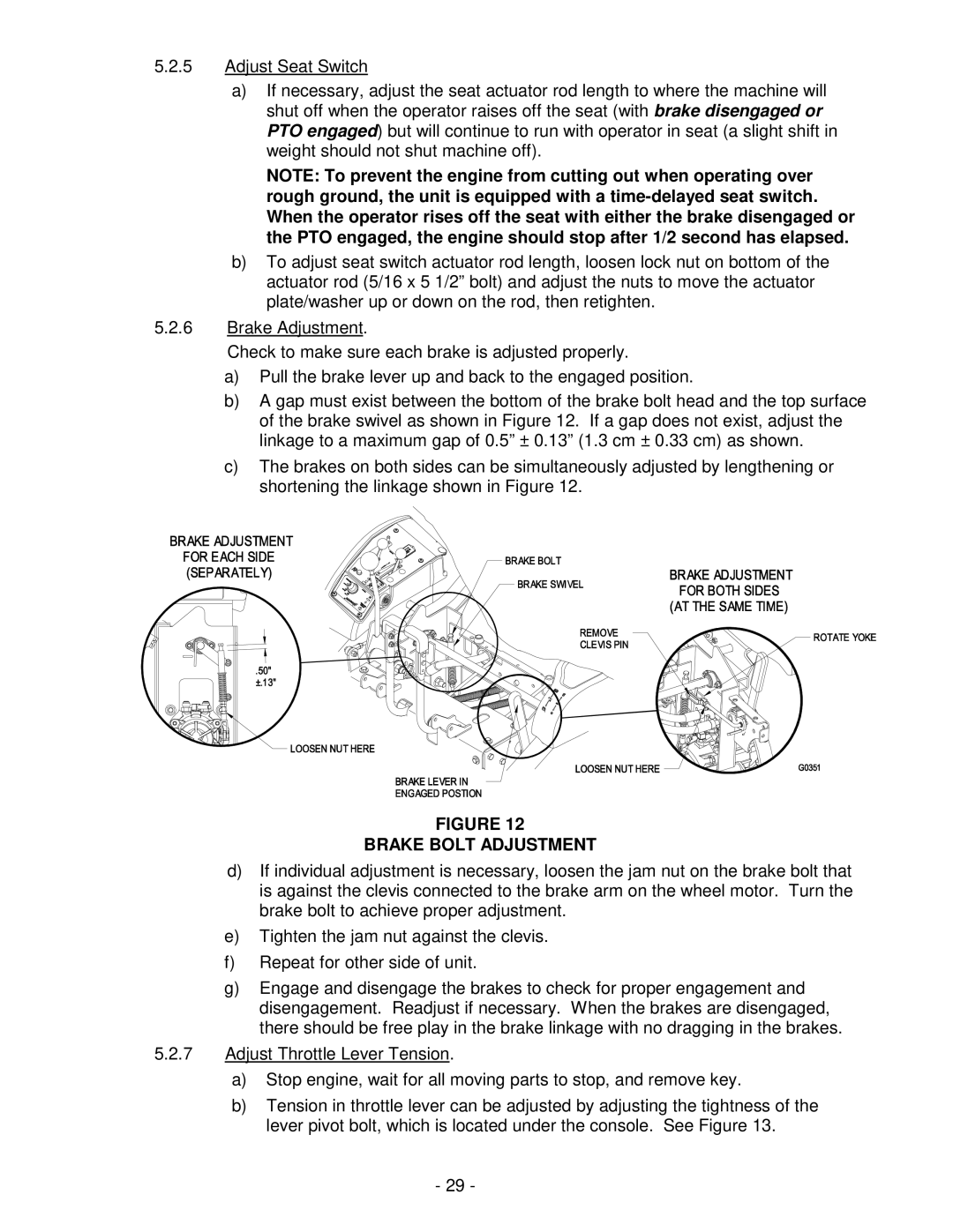
b)A gap must exist between the bottom of the brake bolt head and the top surface of the brake swivel as shown in Figure 12. If a gap does not exist, adjust the linkage to a maximum gap of 0.5” ± 0.13” (1.3 cm ± 0.33 cm) as shown.
c)The brakes on both sides can be simultaneously adjusted by lengthening or shortening the linkage shown in Figure 12.
FIGURE 12
BRAKE BOLT ADJUSTMENT
d)If individual adjustment is necessary, loosen the jam nut on the brake bolt that is against the clevis connected to the brake arm on the wheel motor. Turn the brake bolt to achieve proper adjustment.
e)Tighten the jam nut against the clevis.
f)Repeat for other side of unit.
g)Engage and disengage the brakes to check for proper engagement and disengagement. Readjust if necessary. When the brakes are disengaged, there should be free play in the brake linkage with no dragging in the brakes.
5.2.7Adjust Throttle Lever Tension.
a)Stop engine, wait for all moving parts to stop, and remove key.
b)Tension in throttle lever can be adjusted by adjusting the tightness of the lever pivot bolt, which is located under the console. See Figure 13.
- 29 -