Hardware Installation
17The access point is ready to configure. For information on basic access point device configuration, see “Basic 4700 Series Configuration” on page 31.
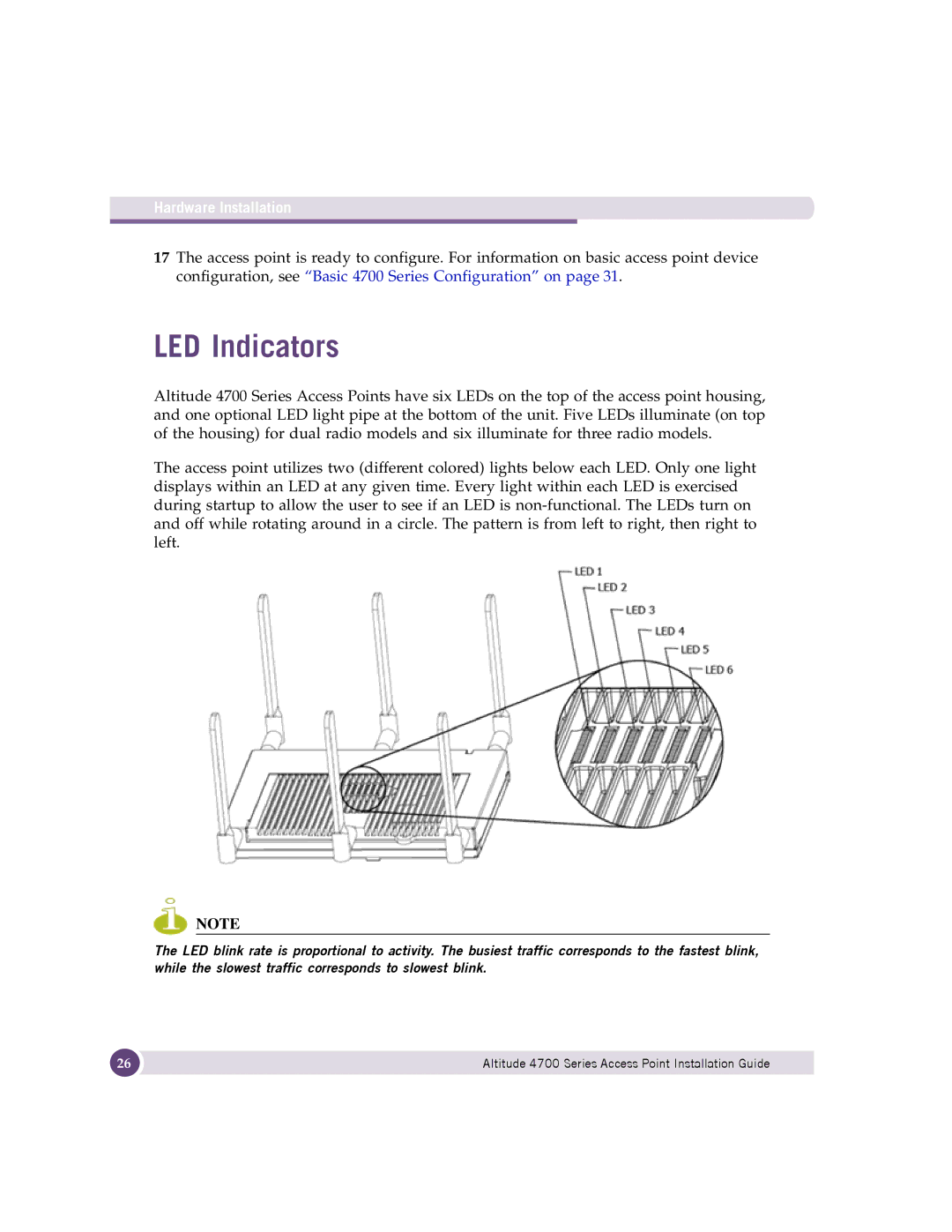
LED Indicators
Altitude 4700 Series Access Points have six LEDs on the top of the access point housing, and one optional LED light pipe at the bottom of the unit. Five LEDs illuminate (on top of the housing) for dual radio models and six illuminate for three radio models.
The access point utilizes two (different colored) lights below each LED. Only one light displays within an LED at any given time. Every light within each LED is exercised during startup to allow the user to see if an LED is
NOTE
The LED blink rate is proportional to activity. The busiest traffic corresponds to the fastest blink, while the slowest traffic corresponds to slowest blink.
26 | Altitude 4700 Series Access Point Installation Guide |
|
|