Serial Communication
The scaler’s
OUTPUTSREMOTE
RGB
RGB
HVS
![]()
![]()
![]()
![]()
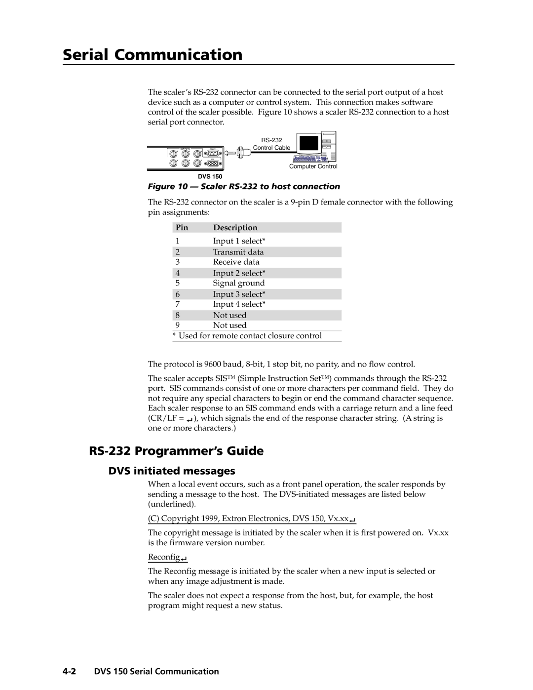
![]() Control Cable
Control Cable
Computer Control
DVS 150
Figure 10 — Scaler RS-232 to host connection
The
Pin Description
1Input 1 select*
2Transmit data
3Receive data
4Input 2 select*
5Signal ground
6Input 3 select*
7Input 4 select*
8Not used
9Not used
*Used for remote contact closure control
The protocol is 9600 baud,
The scaler accepts SIS™ (Simple Instruction Set™) commands through the ![]() ), which signals the end of the response character string. (A string is one or more characters.)
), which signals the end of the response character string. (A string is one or more characters.)
RS-232 Programmer’s Guide
DVS initiated messages
When a local event occurs, such as a front panel operation, the scaler responds by sending a message to the host. The
(C) Copyright 1999, Extron Electronics, DVS 150, Vx.xx![]()
The copyright message is initiated by the scaler when it is first powered on. Vx.xx is the firmware version number.
Reconfig![]()
The Reconfig message is initiated by the scaler when a new input is selected or when any image adjustment is made.
The scaler does not expect a response from the host, but, for example, the host program might request a new status.