Quick Start — DVS 150
Installation
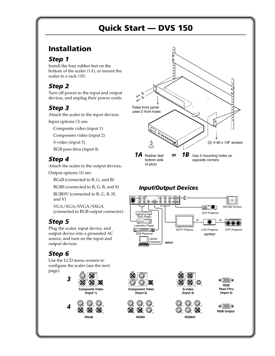
Step 1
Install the four rubber feet on the bottom of the scaler (1A), or mount the scaler in a rack (1B).
Step 2
Turn off power to the input and output devices, and unplug their power cords.
Step 3
Attach the scaler to the input devices.
Input options (3) are:
Composite video (input 1)
Component video (input 2)
RGB
Step 4
Attach the scaler to the output devices.
Output options (4) are:
RGsB (connected to R, G, and B)
RGBS (connected to R, G, B, and S)
RGBHV (connected to R, G, B, H, and V)
VGA/XGA/SVGA/SXGA (connected to RGB output connector)
Step 5
Plug the scaler, input device, and output device into a grounded AC source, and turn on the input and output devices.
False front panel uses 2 front holes
INPUT |
|
|
|
|
1 |
|
|
|
|
2 |
|
|
|
|
3 |
|
|
|
|
4 |
|
|
|
|
CO | LOR |
|
|
|
| TINT |
|
|
|
|
| BRIT |
|
|
|
| CONTR |
|
|
|
| AST H |
|
|
|
| SHIFT |
| (2) |
|
| V |
| |
|
| SHIFT |
| |
|
| DIGITAL V DVS |
| |
|
| RATE |
|
|
|
| IDEO | 100 |
|
|
| SCALER |
| |
1A Rubber feet | or | 1B Use 2 mounting holes on | ||
bottom side |
|
| opposite corners | |
(4 plcs) |
|
|
|
|
Input/Output Devices
VIDEO | INPUTS |
| OUTPUTS | REMOTE | |
|
| R | G | B | |
| 1 |
| RGB |
|
|
| V | RGB | |||
| Y | H | S |
50/60 Hz | 23 | 4 |
|
|
|
|
|
| |
|
|
| DLP Projector |
|
| DVD Player |
|
|
|
|
| or |
| or |
| Laserdisc Player |
|
|
|
|
| HDTV Plasma | LCD Projector | CRT Projector |
| DSS Receiver |
| OUTPUT |
|
|
|
|
|
Laptop
Computer INPUT
Step 6
Use the LCD menu screens to configure the scaler (see the next
page). VID
3 | 1 |
|
2 3
VID |
| VID |
| ||
|
|
|
| ||
1 |
|
| 1 |
|
|
Y |
| Y |
| ||
| 2 | 3 |
| 2 | 3 |
RGB
Composite Video | Component Video | |
(Input 1) | (Input 2) | (Input 3) |
4 | R | G | B | R | G | B | R | G | B |
| H | V | S | H | V | S | H | V | S |
(Input 4)
RGB Output
RGsB | RGBS | RGBHV |