Installation
Rear Panel Features
|
|
|
|
|
|
| 8 |
0.3A | VIDEO | INPUTS |
|
| OUTPUTS | REMOTE | |
|
|
|
| R | G | B | |
|
| 1 | RGB |
|
|
| |
|
| H | V | RGB | |||
|
| Y |
| S | |||
50/60 Hz |
| 2 | 3 | 4 |
|
| |
1 | 2 | 3 | 4 | 5 |
| 6 | 7 |
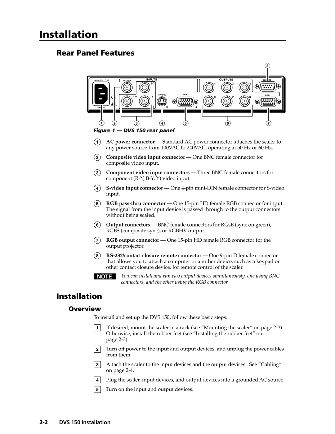
Figure 1 — DVS 150 rear panel
1AC power connector — Standard AC power connector attaches the scaler to any power source from 100VAC to 240VAC, operating at 50 Hz or 60 Hz.
2Composite video input connector — One BNC female connector for composite video input.
3Component video input connectors — Three BNC female connectors for component
4
5RGB
6Output connectors — BNC female connectors for RGsB (sync on green), RGBS (composite sync), or RGBHV output.
7RGB output connector — One
8
You can install and run two output devices simultaneously, one using BNC connectors, and the other using the RGB connector.
Installation
Overview
To install and set up the DVS 150, follow these basic steps:
1
2
3
4
5
If desired, mount the scaler in a rack (see “Mounting the scaler” on page
page
Turn off power to the input and output devices, and unplug the power cables from them.
Attach the scaler to the input devices and the output devices. See “Cabling” on page
Plug the scaler, input devices, and output devices into a grounded AC source.
Turn on the input and output devices.