6
7
Use the LCD menu screens to configure the scaler. See “Configuring the Scaler” on page
The image from the input device should appear on the output device. If it does not, double check steps 3 and 4 and make adjustments as needed, and then see “Operating Problems” on page
Mounting the scaler
Each DVS 150 ships with four uninstalled rubber feet. If you are going to rack mount the unit, do so before cabling it, and do not install the rubber feet. If you are not rack mounting the scaler, skip to “Installing the rubber feet” below.
The DVS 150 can be rack mounted using one side of an optional 19” 1U Universal Rack Shelf (Extron part #
To rack mount the scaler, do the following:
1.If rubber feet were previously installed on the bottom of the case, remove them.
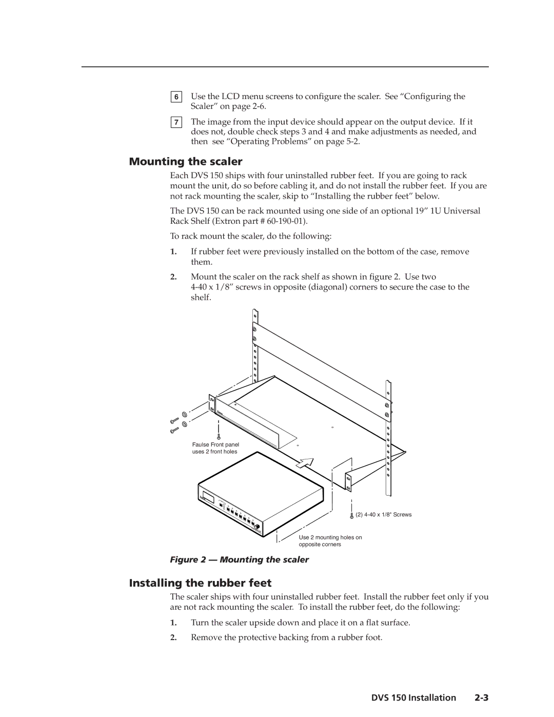
2.Mount the scaler on the rack shelf as shown in figure 2. Use two
Faulse Front panel uses 2 front holes
INPUT
![]() 1 2 3
1 2 3
4 COLOR TINT
BRIT |
|
CONTRAST | H |
| SHIFT |
VSHIFT
RATE |
|
|
|
DIGITAL | DVS | 100 | |
| VIDEO |
| |
|
| SCALER | |
![]() (2)
(2)
Use 2 mounting holes on opposite corners
Figure 2 — Mounting the scaler
Installing the rubber feet
The scaler ships with four uninstalled rubber feet. Install the rubber feet only if you are not rack mounting the scaler. To install the rubber feet, do the following:
1.Turn the scaler upside down and place it on a flat surface.
2.Remove the protective backing from a rubber foot.
DVS 150 Installation |