Installation, cont’d
3.Place the rubber foot on one corner of the scaler, and press it into place.
Position the rubber foot carefully before pressing it into place. It is difficult to move the foot after it is in place.
4.Repeat steps 2 and 3 to install a rubber foot on each of the remaining corners of the scaler.
5.Turn the scaler right side up and place it in the desired location.
Cabling
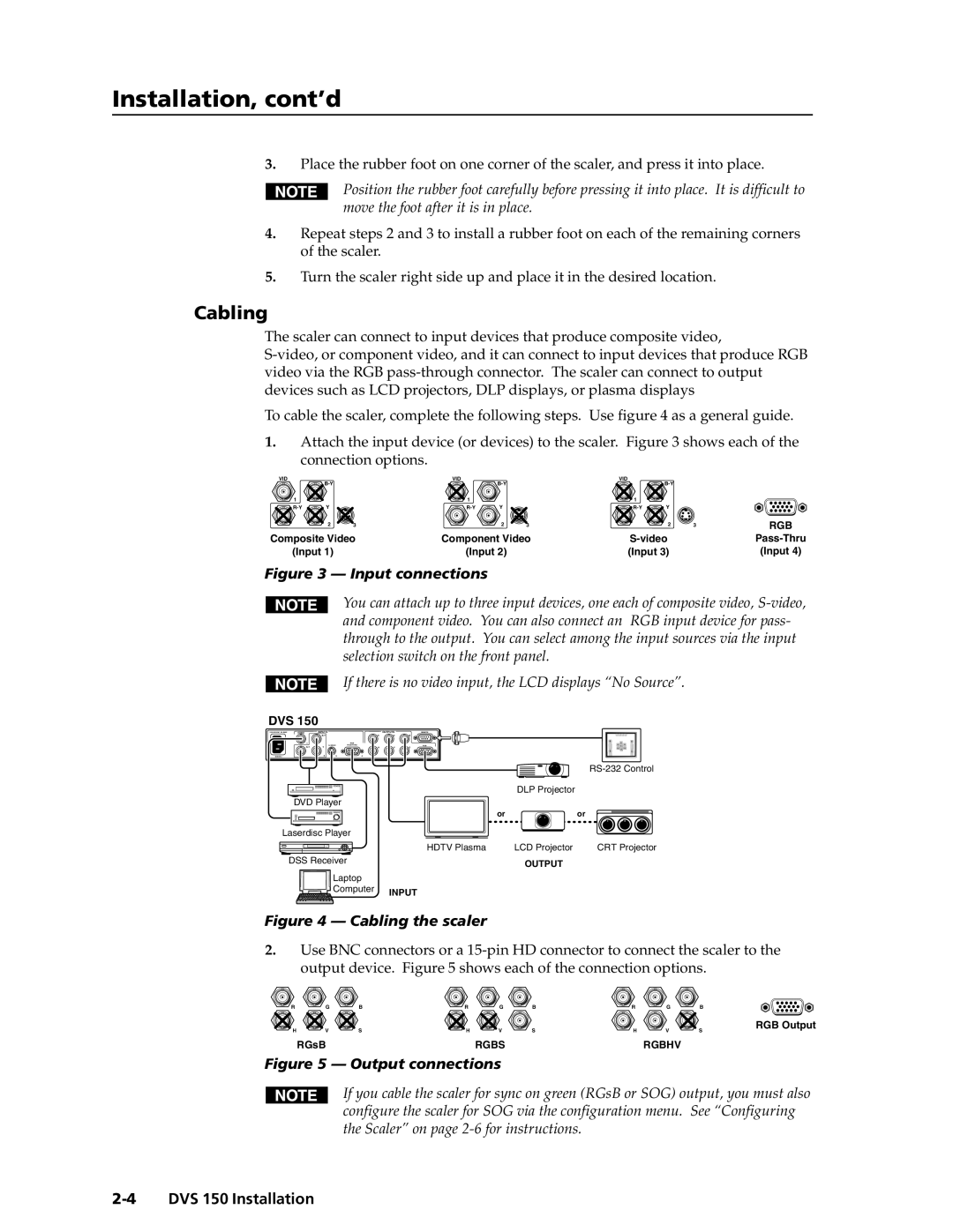
The scaler can connect to input devices that produce composite video,
To cable the scaler, complete the following steps. Use figure 4 as a general guide.
1.Attach the input device (or devices) to the scaler. Figure 3 shows each of the
connection options.
VID |
| VID |
| VID |
|
| |||
|
|
|
|
|
|
| |||
1 |
|
| 1 |
|
| 1 |
|
|
|
Y |
| Y |
| Y |
|
| |||
| 2 | 3 |
| 2 | 3 |
| 2 | 3 | RGB |
Composite Video | Component Video |
| |||||||
(Input 1) |
| (Input 2) |
| (Input 3) |
| (Input 4) | |||
Figure 3 — Input connections
You can attach up to three input devices, one each of composite video,
If there is no video input, the LCD displays “No Source”.
DVS 150
50/60 Hz
VIDEO | INPUTS |
| OUTPUTS | REMOTE |
| R | G | B | |
1 |
| RGB |
|
|
V | RGB | |||
Y | H | S |
2 | 3 | 4 |
|
|
| |
|
| DLP Projector |
|
DVD Player |
|
|
|
| or |
| or |
Laserdisc Player |
|
|
|
| HDTV Plasma | LCD Projector | CRT Projector |
DSS Receiver |
| OUTPUT |
|
|
|
| |
Laptop |
|
|
|
Computer | INPUT |
|
|
|
|
|
Figure 4 — Cabling the scaler
2.Use BNC connectors or a
R | G | B | R | G | B | R | G | B |
H | V | S | H | V | S | H | V | S |
| RGsB |
|
| RGBS |
|
| RGBHV |
|
Figure 5 — Output connections
RGB Output
If you cable the scaler for sync on green (RGsB or SOG) output, you must also configure the scaler for SOG via the configuration menu. See “Configuring the Scaler” on page
