You can install and run two output devices simultaneously, one using BNC connectors, and the other using the RGB connector.
Front Panel Features
| INPUT |
|
|
|
|
|
|
|
|
| |
|
|
| 1 |
|
|
|
|
|
|
|
|
|
|
| 2 |
|
|
|
|
|
|
|
|
|
|
| 3 |
|
|
|
|
|
|
|
|
|
|
| 4 | COLOR | TINT | BRIGHT | CONT | HSHIFT | VSHIFT | RATE |
|
|
|
|
|
|
|
|
|
|
| DVS 150 | |
|
|
|
|
|
|
|
|
|
|
| |
|
|
|
|
|
|
|
|
|
| DIGITAL VIDEO SCALER | |
1 | 2 | 3 |
| 4 | 5 | 6 | 7 | 8 | 9 | 10 | 11 |
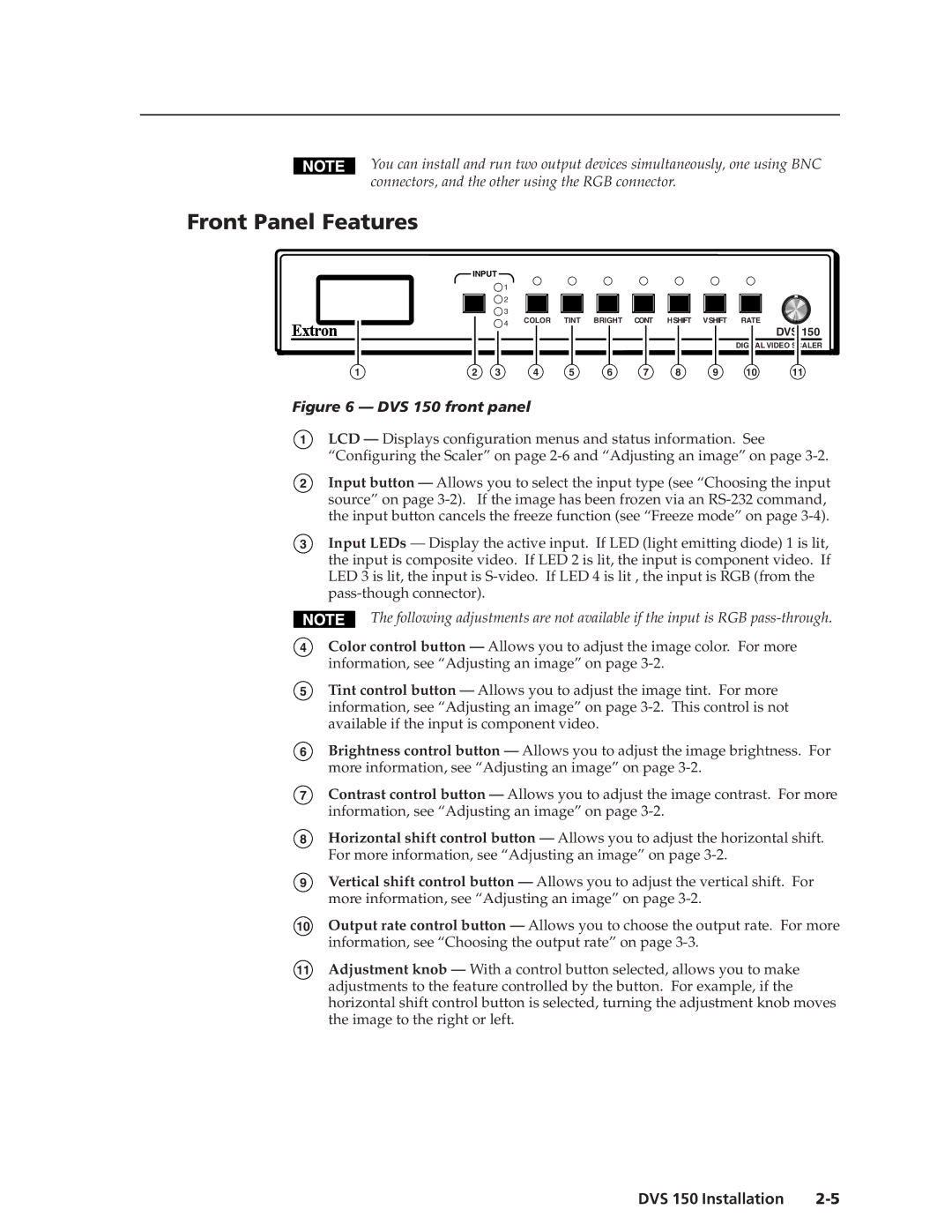
Figure 6 — DVS 150 front panel
1
2
LCD — Displays configuration menus and status information. See
“Configuring the Scaler” on page
Input button — Allows you to select the input type (see “Choosing the input source” on page
3Input LEDs — Display the active input. If LED (light emitting diode) 1 is lit, the input is composite video. If LED 2 is lit, the input is component video. If LED 3 is lit, the input is
The following adjustments are not available if the input is RGB
4
5
Color control button — Allows you to adjust the image color. For more information, see “Adjusting an image” on page
Tint control button — Allows you to adjust the image tint. For more information, see “Adjusting an image” on page
6Brightness control button — Allows you to adjust the image brightness. For more information, see “Adjusting an image” on page
7Contrast control button — Allows you to adjust the image contrast. For more information, see “Adjusting an image” on page
8Horizontal shift control button — Allows you to adjust the horizontal shift. For more information, see “Adjusting an image” on page
9Vertical shift control button — Allows you to adjust the vertical shift. For more information, see “Adjusting an image” on page
10Output rate control button — Allows you to choose the output rate. For more information, see “Choosing the output rate” on page
11Adjustment knob — With a control button selected, allows you to make adjustments to the feature controlled by the button. For example, if the horizontal shift control button is selected, turning the adjustment knob moves the image to the right or left.
DVS 150 Installation |
