CrossPoint 450 Plus Series MAV Plus series
Large Scale Matrix Switchers
68-521-03 Rev. A
Safety Instructions English
Precautions
Consignes de Sécurité Français
Sicherheitsanleitungen Deutsch
Installation of multiple BME system
Quick Start - CrossPoint 450 Plus and MAV Plus Switchers
I/O Connections
Step 1 - Numbering the BMEs
Step 6 - Power
Quick Start - CrossPoint 450 Plus and MAV Plus Switchers, cont’d
Front Panel Controls
Step 4 - Outputs
CrossPoint 450 Plus and MAV Plus Switchers Table of Contents
Table of Contents
Optimizing the Audio Systems with Audio BMEs
Table of Contents, cont’d
ii CrossPoint 450 Plus and MAV Plus Switchers Table of Contents
Chapter Four SIS Programming and Control
CrossPoint 450 Plus and MAV Plus Switchers Table of Contents
iv CrossPoint 450 Plus and MAV Plus Switchers Table of Contents
CrossPoint 450 Plus and MAV Plus Switchers Table of Contents
68-521-03 A
vi CrossPoint 450 Plus and MAV Plus Switchers Table of Contents
About this Manual About the Matrix Switchers Definitions Features
CrossPoint 450 Plus and MAV Plus Switchers
Chapter1One
Introduction
About the Matrix Switchers
Installation
About this Manual
1-2 CrossPoint 450 Plus and MAV Plus Switchers Introduction
Figure 1-1 - CrossPoint 450 Plus / MAV Plus application
CrossPoint 450 Plus and MAV Plus Switchers Introduction
1-4 CrossPoint 450 Plus and MAV Plus Switchers Introduction
Introduction, cont’d
Definitions
Features
Input #
1-6 CrossPoint 450 Plus and MAV Plus Switchers Introduction
Figure 1-2 - DSVP data display
Tie any input to any or all outputs
1-8 CrossPoint 450 Plus and MAV Plus Switchers Introduction
Mounting the Switcher Rear Panel Views Front Panel Configuration Port
Installation
Chapter2Two
Rear Panel Views
Mounting the Switcher
2-2 CrossPoint 450 Plus and MAV Plus Switchers Installation
CrossPoint 450 Plus and MAV Plus Switchers Installation
Video or sync input and output video and sync BMEs
Figure 2-2 - MAV Plus 6464 Stereo Audio BME
Sync termination switches systems with sync BMEs
Installation, cont’d
Audio input and output systems wtih audio BMEs
Figure 2-3 - Captive screw connector wiring for stereo audio inputs
Figure 2-5 - Typical audio connectors
Figure 2-4 - Captive screw connector wiring for mono audio inputs
Figure 2-6 - Captive screw connector wiring for stereo audio output
Figure 2-7 - Captive screw connector wiring for mono audio output
BME connection and selection
Figure 2-8 - Setting a BME address video BME shown
2-6 CrossPoint 450 Plus and MAV Plus Switchers Installation
From BME
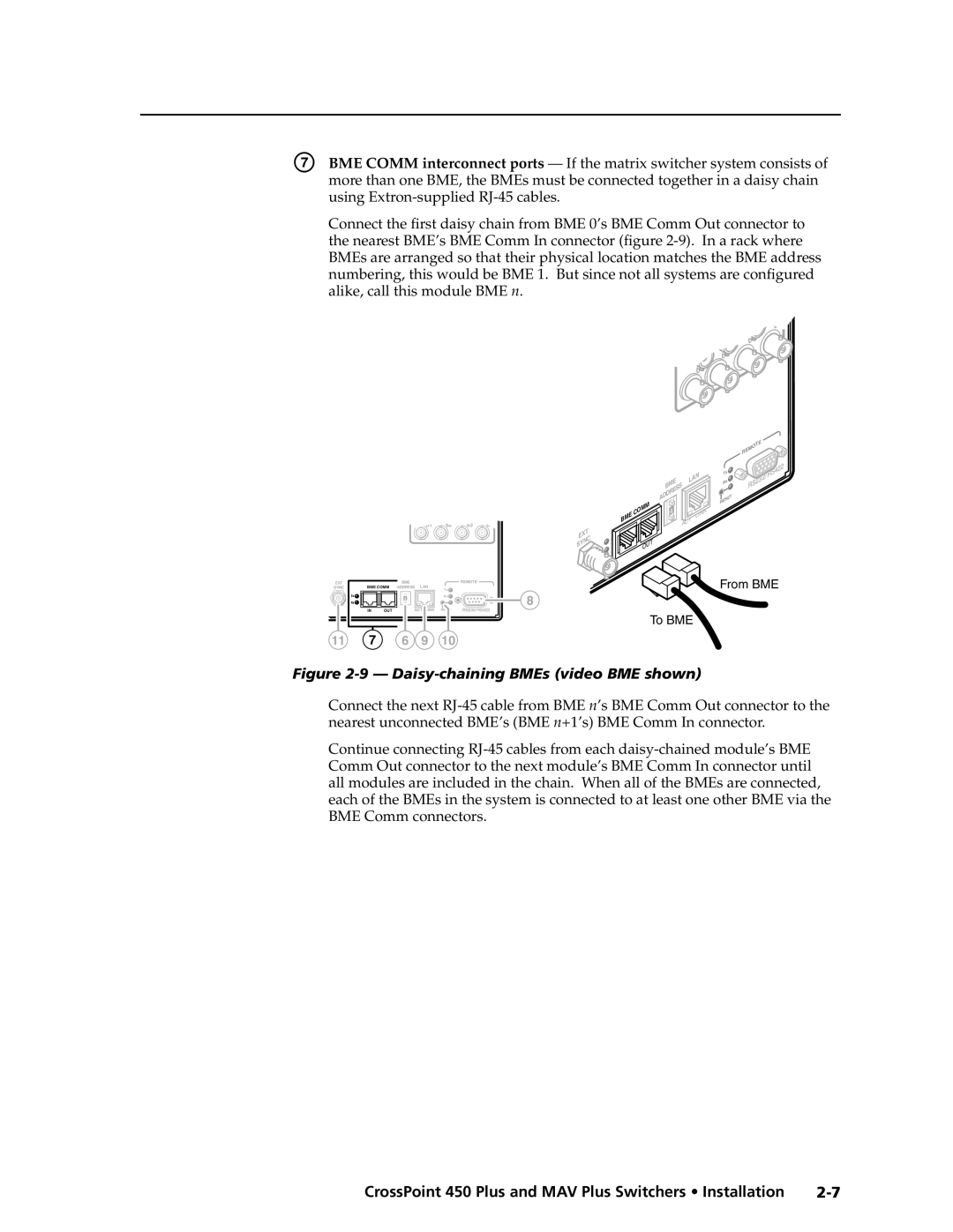
Figure 2-9 - Daisy-chaining BMEs video BME shown
Ethernet
RS-232/RS-422
Figure 2-10 - RS-232/RS-422 connector
2-8 CrossPoint 450 Plus and MAV Plus Switchers Installation
Figure 2-11 - RJ-45 connector and pinout tables
Cabling and RJ-45 connector wiring
External sync systems with MAV Plus Video BMEs
Reset button
2-10 CrossPoint 450 Plus and MAV Plus Switchers Installation
Figure 2-12 - Simple external sync connection example
Power
Figure 2-13 - Multiple device external sync connection example
Extron MAV Plus
2-12 CrossPoint 450 Plus and MAV Plus Switchers Installation
Front Panel Configuration Port
Computers signal ground
POWER SUPPLY
Troubleshooting Configuration Worksheets
Front Panel Controls and Indicators QS-FPC Front Panel Operations
Chapter3Three
Operation
Operation
Front Panel Controls and Indicators
3-2 CrossPoint 450 Plus and MAV Plus Switchers Operation
Figure 3-1 - CrossPoint 450 Plus 6464 series with integrated QS-FPC
Input and output buttons
Definitions
CrossPoint 450 Plus and MAV Plus Switchers Operation
Control buttons
Operation, cont’d
3-4 CrossPoint 450 Plus and MAV Plus Switchers Operation
In the I/O Group mode, select group 2. See I/O grouping on page
3-6 CrossPoint 450 Plus and MAV Plus Switchers Operation
g RGBHV CrossPoint 450 Plus button or Video MAV Plus button - The
I/O controls
Button icons
Power indicators
3-8 CrossPoint 450 Plus and MAV Plus Switchers Operation
30 31
Creating a configuration
QS-FPC Front Panel Operations
Example 1 Creating a set of video and audio ties
3-10 CrossPoint 450 Plus and MAV Plus Switchers Operation
Figure 3-4 - Clear all selections
Figure 3-5 - Select RGBHV or video and audio
1 2 3 4 5 6
1 2 3 4 5 6 7 17 18 19 20 21 22 23
17 18 19 20 21 22 23
Press the Enter button to confirm the configuration change
3-12 CrossPoint 450 Plus and MAV Plus Switchers Operation
17 18 19 20 21 22 23
The button is unlit or background illuminated when deselected
Example 2 Adding a tie to a set of video and audio ties
Input 5 video tied to outputs 1, 3, 4, and Input 5 audio tied
Figure 3-14 - Press the Enter button
to outputs 3, 4, and
Figure 3-15 - Example 2, final configuration
Example 3 Removing a tie from a set of video and audio ties
3-14 CrossPoint 450 Plus and MAV Plus Switchers Operation
Figure 3-16 - Clear all selections
Figure 3-17 - Select audio only
Figure 3-19 - Deselect the output
Figure 3-21 - Example 3, final configuration, audio switcher
Figure 3-20 - Press the Enter button
Input 5 video tied to outputs 1, 3, 4, and
3-16 CrossPoint 450 Plus and MAV Plus Switchers Operation
Viewing a configuration
Example 4 Viewing video and audio, audio only, and video only ties
49 50 51 52 53 54 55
Figure 3-22 - Clear all selections
Figure 3-23 - Select RGBHV or video and audio
Figure 3-25 - Deselect RGBHV or video to view audio ties only
3-18 CrossPoint 450 Plus and MAV Plus Switchers Operation
Press and release the Input 5 button. The button lights amber
Amber for audio and RGBHV or video ties audio follow
Figure 3-27 - Press the View button to exit View-Only mode
3-20 CrossPoint 450 Plus and MAV Plus Switchers Operation
I/O grouping
17 18 19 20 21 22 23 24
33 34 35 36 37 38 39 40 41
3. Press and release one of the Control buttons to select a group
3-22 CrossPoint 450 Plus and MAV Plus Switchers Operation
1 2 17
1 2 17
Example 5 Grouping inputs and outputs
Figure 3-32 - Assign inputs and outputs
17 18 19 20 21 22 23 17 18 19 20 21 22 23
Figure 3-33 - Select an I/O group
Figure 3-34 - Assign inputs and outputs
Example 6 Setting the RGB delay for an output
Setting RGB delay systems with wideband BMEs
3-24 CrossPoint 450 Plus and MAV Plus Switchers Operation
Figure 3-35 - Clear all selections
17 18 19 20 21 22 23
1 2 3 4 5 6 7 8 9
17 18 19 20 21 22 23 24 25 26
Figure 3-38 - Adjust the RGB delay interval
Example 7 Saving a preset
Using presets
3-26 CrossPoint 450 Plus and MAV Plus Switchers Operation
Figure 3-39 - Deselect RGB Delay mode
1 2 3 4 5 6 7 1718192021222324
17 18
Figure 3-41 - Enter Save Preset mode
Figure 3-42 - Select the preset
Figure 3-45 - Enter Recall Preset mode
Example 8 Recalling a preset
Figure 3-46 - Select the preset
3-28 CrossPoint 450 Plus and MAV Plus Switchers Operation
Muting and unmuting video and/or audio outputs
1718
Figure 3-47 - Press the Enter button
Example 9 Muting and unmuting an output
3-30 CrossPoint 450 Plus and MAV Plus Switchers Operation
Figure 3-48 - Clear all selections
Figure 3-49 - Select RGBHV or video and audio
Figure 3-51 - Unmute the outputs
Figure 3-50 - Mute the outputs
3-32 CrossPoint 450 Plus and MAV Plus Switchers Operation
Viewing and adjusting the input audio level systems with audio BMEs
Figure 3-52 - Press the View button to exit View-Only mode
Figure 3-53 - Audio gain and attenuation
Figure 3-54 - Clear all selections
Example 10 Viewing and adjusting an input audio level
Figure 3-55 - Select Audio mode
1 2 3 4 5 6 7 8 9 17 18 19 20 21 22 23 24 25 26 O
1718192021222324 2526 O
Figure 3-57 - Adjust the input audio level
3-34 CrossPoint 450 Plus and MAV Plus Switchers Operation
Figure 3-58 - Deselect Audio mode
Viewing and adjusting the output volume systems with audio BMEs
3-36 CrossPoint 450 Plus and MAV Plus Switchers Operation
Reading the displayed volume
= blinking LED
Audio volume adjustment settings
None
Example 11 Viewing and adjusting an output volume level
10 11 12 13
3-38 CrossPoint 450 Plus and MAV Plus Switchers Operation
24 25 26 27 28 29 30 31
22 23 24 25
11 12 13
Figure 3-62 - Adjust the output audio volume
32.5 dB attenuation 51.25% volume
Locking out the front panel Executive mode
Performing a system reset from the front panel
Power
Figure 3-65 - System reset
Figure 3-66 - Toggle background illumination on or off
Background illumination
3-42 CrossPoint 450 Plus and MAV Plus Switchers Operation
Selecting the rear panel Remote port protocol and baud rate
Figure 3-67 - RS-232/RS-422 and baud rate display
Release the Control buttons
Rear Panel Controls
Performing soft system resets
3-44 CrossPoint 450 Plus and MAV Plus Switchers Operation
Figure 3-70 - Whole switcher and absolute resets
Optimizing the Audio Systems with Audio BMEs
Performing a hard reset
Figure 3-71 - Hard reset
Plasma display S-video problem CrossPoint 450 Plus wideband BMEs only
Troubleshooting
Configuration Worksheets
General checks
Figure 3-72 - Worksheet example 1 System equipment
Preset #
Input sources
21 22
3-48 CrossPoint 450 Plus and MAV Plus Switchers Operation
Worksheet example 2 Daily configuration
Figure 3-73 - Worksheet example 2 Daily configuration
3-50 CrossPoint 450 Plus and MAV Plus Switchers Operation
Worksheet example 3 Test configuration
Figure 3-74 - Worksheet example 3 Test configuration
Preset #
Blank configuration worksheet
Input sources
Output destinations
3-52 CrossPoint 450 Plus and MAV Plus Switchers Operation
Switcher-Initiated Messages Switcher Error Responses
RS-232 and RS-422 Links Ethernet Link Host-to-Switcher Instructions
Using the Command/Response Tables
Command/Response Table for SIS Commands
RS-232 and RS-422 Links
SIS Programming and Control
Rear panel Remote port
Figure 4-1 - Remote connector pin assignments
Figure 4-2 - Optional 9-pin TRS RS-232 cable
Front panel Configuration port
SIS Programming and Control, cont’d
Default IP addresses
Ethernet Link
Ethernet connection
Switcher-Initiated Messages
Host-to-Switcher Instructions
Using the Command/Response Tables
Switcher Error Responses
X1! =
Symbol definitions
X1# =
X1$ =
Command
Command/response table for SIS commands
ASCII command
Response
Digital Sync Validation Processing DSVP
Command/response table for SIS commands continued
RGB / Video mute
RGB delay
Audio mute
Audio output volume
Names
Audio output volume settings table
X1 1X1 2X1 3 ... X1 n
EX1 1X1 2X1 3 ... X1 n O
GroX1 1X1 2X1 3 ... X1 n
I/O grouping
E+27P22*5!15*29%13*26$3*8
Save, recall, and directly write presets
X2!,Y!,Y@,Y#, ..., Y
Resets
Save, recall, and directly write presets continued
Front panel security lockout Executive mode
ZppX**X1@
CrossPoint 450 Plus
View ties, gain, volume, mutes, presets, and DSVP
View ties, gain, volume, mutes, presets, and DSVP continued
EX1! *X# *2VC
Command description
X@ nX@ n+1X@ n+2 ... X@ n+15 Aud
Command
MAV 450 Plus
Information requests
with a connected audio
X2@X2@X2@X2@X2@X2@X2@X2#X2$X2$XX
Command/Response table for IP SIS commands
= RAM has been saved ok to power off / reset
= Administrator
Security level
= Anonymous
Command/response table for IP SIS commands
Special Characters
Chapter5Five
Matrix Switchers Control Program Special Characters
Matrix Software
Button-Label Generator
Installing the software
Matrix Switchers Control Program
Matrix Software
Software operation via Ethernet
Ethernet protocol settings
Using the software
CrossPoint 450 Plus and MAV Plus Switchers Matrix Software
Figure 5-1 - Comm port selection window
Figure 5-2 - Address and password entry
Matrix Software, cont’d
5-4 CrossPoint 450 Plus and MAV Plus Switchers Matrix Software
Figure 5-3 - Matrix Switcher Control Program window no ties or icons
5-6 CrossPoint 450 Plus and MAV Plus Switchers Matrix Software
Figure 5-5 - Control program IP setting/options window
IP Settings/Options window
Matrix IP Address field
5-8 CrossPoint 450 Plus and MAV Plus Switchers Matrix Software
Extron Name/Descriptor field
Subnet Mask field
Gateway IP address field
Hardware Address field
Use DHCP checkbox
Time local field
5-10 CrossPoint 450 Plus and MAV Plus Switchers Matrix Software
Sync Time to PC button
GMT offset field
User Password field
Administrator Password field
Mail Server IP Address field
5-12 CrossPoint 450 Plus and MAV Plus Switchers Matrix Software
Mail Server Domain Name field
N The following characters are invalid in a domain name
E-mail Addressee fields
Miles Standish
Figure 5-6- Typical CrossPoint 450 Plus e-mail
5-14 CrossPoint 450 Plus and MAV Plus Switchers Matrix Software
Update firmware
Figure 5-7 - Open window
Figure 5-8 - HTML Files List window
Upload HTML files
Windows menus
Windows buttons, drop boxes, and trash
5-16 CrossPoint 450 Plus and MAV Plus Switchers Matrix Software
File menu
Tools menu
Audio-Output volume settings - Displays the audio
Figure 5-9 - Status window
5-18 CrossPoint 450 Plus and MAV Plus Switchers Matrix Software
White - Components are not installed
Green - Proper operation Red - Component has failed
Preferences menu
Figure 5-11 - Ties shown as crosspoints
Master-Reset selection
set this option to Automatically every 10 seconds
Using the help system
Using emulation mode
Button-Label Generator
5-20 CrossPoint 450 Plus and MAV Plus Switchers Matrix Software
HTML Operation
Chapter66
Download the Startup Page System Status Page System Configuration Page
File Management Page Set and View Ties Page Special Characters
Download the Startup Page
HTML Operation
Figure 6-1 - Enter Network Password page
6-2 CrossPoint 450 Plus and MAV Plus Switchers HTML Operation
CrossPoint 450 Plus and MAV Plus Switchers HTML Operation
System Status Page
Figure 6-2 - System Status page
DSVP page systems with a sync BME only
HTML Operation, cont’d
6-4 CrossPoint 450 Plus and MAV Plus Switchers HTML Operation
Figure 6-3 - DSVP page
Figure 6-4 - System Configuration page
System Configuration Page
6-6 CrossPoint 450 Plus and MAV Plus Switchers HTML Operation
IP Settings fields
Unit Name field
DHCP radio buttons
Figure 6-5 - Date/Time Settings fields
Date/Time Settings fields
Figure 6-6 - Passwords page
Passwords page
6-8 CrossPoint 450 Plus and MAV Plus Switchers HTML Operation
Figure 6-7 - Email Settings page
Email Settings page
Mail IP Address field
Domain Name field
Figure 6-8 - Firmware Upgrade page
Firmware Upgrade page
6-10 CrossPoint 450 Plus and MAV Plus Switchers HTML Operation
Email address fields
CrossPoint 450 Plus and MAV Plus Switchers HTML Operation
6-12 CrossPoint 450 Plus and MAV Plus Switchers HTML Operation
File Management Page
Figure 6-9 - File Management page
Figure 6-10 - Set and View Ties page
Set and View Ties Page
The amber buttons indicate video and audio ties
Create a tie
RGBHV and Audio Settings page
Figure 6-11 - RGB and Audio Settings page
6-14 CrossPoint 450 Plus and MAV Plus Switchers HTML Operation
Figure 6-12 - Input selection drop box
Change the input gain and attenuation systems with audio BMEs
Figure 6-13 - Input Audio Level drop box
Mute and unmute one or all outputs
6-16 CrossPoint 450 Plus and MAV Plus Switchers HTML Operation
Figure 6-14 - Output selection drop box
Figure 6-15 - Mute status indications
Figure 6-16 - Output selection drop box
Change the RGB delay sytems with CrossPoint 450 Plus sync BMEs
Figure 6-17 - RGB delay drop box
Figure 6-19 - Volume drop box
Change the output volume level systems with audio BMEs
6-18 CrossPoint 450 Plus and MAV Plus Switchers HTML Operation
Figure 6-18 - Output selection drop box
Audio volume adjustment settings
Figure 6-20 - Global Presets page
Global Presets page
Save a preset
Recall a preset
Special Characters
6-22 CrossPoint 450 Plus and MAV Plus Switchers HTML Operation
Ethernet Connection
AAppendix A
Ethernet Link Subnetting - A Primer
Ethernet Connection
Default address
Figure A-1 - RJ-45 connector pinout tables
A-2 CrossPoint 450 Plus and MAV Plus Switchers Ethernet Connection
Pinging to determine Extron IP address
CrossPoint 450 Plus and MAV Plus Switchers Ethernet Connection
Figure A-2 - Ping response
Pinging to determine Web IP address
Ethernet Connection, cont’d
Connecting as a Telnet client
A-4 CrossPoint 450 Plus and MAV Plus Switchers Ethernet Connection
Figure A-3 - Telnet screen
Local echo
Escape character and Esc key
Set carriage return-line feed
Close
Gateways
Subnetting - A Primer
Local and remote devices
IP addresses and octets
Unmasked octets are compared indicated by ? in figure A-6
Determining whether devices are on the same subnet
Masked octets are not compared indicated by X in figure A-6
Figure A-6 - Comparing the IP addresses
A-8 CrossPoint 450 Plus and MAV Plus Switchers Ethernet Connection
AppendixBB
Part Numbers and Accessories Button Labels
Reference Information
CrossPoint 450 Plus Specifications MAV Plus Specifications
CrossPoint 450 Plus Specifications
Reference Information
Video
Video input
General
Control/remote - switcher
CrossPoint 450 Plus and MAV Plus Switchers Reference Information
MAV Plus Specifications
Reference Information, cont’d
Audio - audio BMEs
B-4 CrossPoint 450 Plus and MAV Plus Switchers Reference Information
Audio output - audio BMEs
Audio input - audio BMEs
N 0 dBu = 0.775 Vrms, 0 dBV = 1 Vrms, 0 dBV 2 dBu
B-6 CrossPoint 450 Plus and MAV Plus Switchers Reference Information
CrossPoint 450 Plus system part numbers
Part Numbers and Accessories
Model
Part number
B-8 CrossPoint 450 Plus and MAV Plus Switchers Reference Information
MAV Plus system part numbers
BME part numbers
CrossPoint 450 Plus sync BMEs
CrossPoint 450 Plus wideband video BMEs
MAV Plus video BMEs
MAV Plus stereo audio BMEs
Replacement parts
MAV Plus mono audio BMEs
Included parts
Cables
Optional accessories
Adapters, power supplies, labels
RG6 super high resolution cable
Terminated cable assemblies
MHR mini high resolution cable
Button Labels
Installing labels in the matrix switcher’s buttons
Button label blanks
Reference Information, cont’d
FCC Class A Notice
Extron’s Warranty
USA, Canada, South America
Europe, Africa, and the Middle East
Extron Electronics, Europe
Extron Electronics, USA
Extron Electronics, Asia
Extron Electronics, Japan