MPX 866 a
Safety Instructions English
FCC Class a Notice
Extron Electronics. All rights reserved
Contents
113
120
About this Guide
Typical MPX 866 a Application
About the Media Presentation Matrix Switcher
Definitions
Features
Bandwidth
Zz Tie any input to any or all outputs within a video group
MPX 866 a Media Presentation Matrix Switcher Introduction
Install Software
Setup and Installation Checklist
Perform Physical Installation
Install the Matrix Switchers Control Program
Video Input and Output
Rear Panel Cabling and Features
Computer video group
Composite video outputs Video Output 7 and Video Output
Low resolution video group
Video Input 11 through Video Input
Video outputs Video Output 9 and Video Output
Audio input and output
Audio inputs either input subgroup
Captive screw connector wiring for stereo audio output
Audio outputs computer/audio output subgroup only
RS-232 connector
Serial Ports
Ethernet Connection
RJ-45 connector wiring
Cabling
Reset Button and LED
Power
Front Panel Configuration Port
Front Panel Configuration Port
Front Panel Controls and Indicators
Operation
Input and Output Buttons and LEDs
Input buttons and LEDs
Output buttons and LEDs
Control Buttons and LEDs
MPX 866 a Media Presentation Matrix Switcher Operation
See Muting and Unmuting Video and Audio Outputs on
Mode 2 and mode Resets Action
Locks Toggle between mode 0 and mode Action
Controls
Front Panel Operations
Input and Output Label Panels
Front Panel Security Lockouts
Creating a Configuration
Select an input Press and release the input 5 button
Example 1 Creating a set of computer video and audio ties
Confirm the change Press and release the Enter button
Example 1, final configuration
Select the output Press and release the output 1 button
Example 2, final configuration
Example 3, final configuration, audio switcher
Select the output Press and release the output 4 button
Video Inputs
Example 4, final configuration
Viewing a Configuration
Example
Deselect video Press and release the Video button
See Setting the Front Panel Locks Executive Modes on
Muting and Unmuting Video and Audio Outputs
Example 6 Muting and unmuting an output
Using Global Presets
Exit View-onlymode Press and release the View button
Example 7 Saving a global preset
Example 8 Recalling a global preset
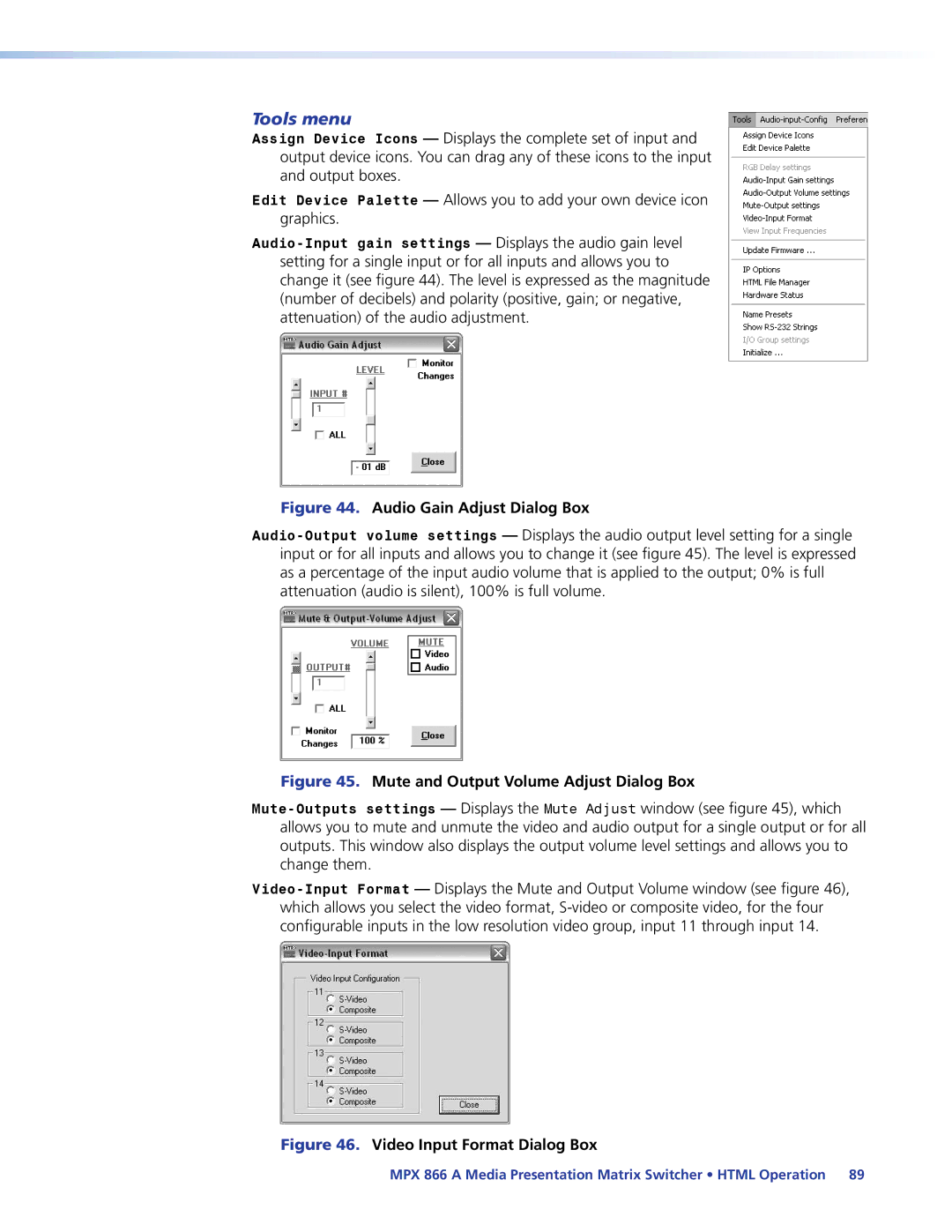
Selecting Composite Video or S-video
Example 9 Selecting the S-video format for an input
Exit the Video mode Press and release the Video button
Viewing and Adjusting the Input Audio Level
Audio gain and attenuation
Input Audio Level Adjustment Displays
Example 10 Viewing and adjusting an input audio level
Adjust the Input Audio Level
Exit the Audio mode Press and release the Audio button
Viewing and Adjusting the Output Volume
Reading the displayed volume
Preset button changes to Recall Preset mode
Zz Push Esc button twice
Audio Output Volume Settings
Zz Push Esc button
Zz Push Esc button 19 times
Example 11 Viewing and adjusting an output volume level
Select an output Press and release the output 1 button
Setting the Front Panel Locks Executive Modes
Adjust the Output Audio Volume
Selecting Lock mode 2 or toggling between mode 2 and mode
Toggle Front Panel Lock Between Mode 2 and Mode
Performing a System Reset from the Front Panel
System Reset
Setting the Front Panel Locks Executive Modes on
Selecting the Baud Rate of the RS-232 Primary Port
Rear Panel Operations
See Matrix Software
Performing Soft System Resets Modes 3, 4,
Perform a soft reset of the switcher as follows
Performing a Hard Reset
Optimizing the Audio
Configuration Worksheets
Troubleshooting
Worksheet Example 1 System Equipment
Worksheet Example 2 Daily Configuration
Worksheet Example 2 Daily Configuration
Worksheet Example 3 Test Configuration
Worksheet Example 3 Test Configuration
Blank Configuration Worksheet
Computer video and audio subgroup input sources
Programming Guide
RS-232 Ports
Front Panel Configuration Port
Rear Panel Remote Ports
Ethernet LAN Port
Default IP Addresses
0.0 Dhcp off
Establishing a Connection
Connection Timeouts
Using Verbose Mode
Number of Connections
Host-to-Switcher Instructions
Switcher-initiated Messages
Switcher Error Responses
Using the Command and Response Tables
X1 =
Command and Response Table for SIS Commands
Symbol Definitions
X1! =
Command and Response Table for SIS Commands
Command Ascii Command Response Additional description
Command/Response Table for SIS Commands
Read ties
Audio output volume
Audio input gain and attenuation
Preset names
Input signal active
Lock executive modes
X2$
Command and Response Table for IP-Specific SIS Commands
X2#
X3% =
Command and Response Table for IP-Specific SIS Commands
Special Characters
Matrix Switchers Control Program
Installing the Software
Software operation via a serial port
Software operation via Ethernet
Using the Matrix Switcher Control Software
Comm Port Selection window see appears
Address and Password Entry
If the IP address is correct, proceed to b
Extron Matrix Switchers Control Program Window Blank
IP Settings/Options window
Address and Name fields
Hardware Address field
Use Dhcp check box
Sync Time to PC button
Date, Time local, and GMT offset fields
Use Daylight Savings check box
Administrator Password and User Password fields
Location of Firmware Upgrade Files
Updating firmware
Downloading Firmware Upgrade Files
Ethernet-connected firmware upload
Select Files Window Dialog Box
Serial-port-connected firmware upload
Click Exit to close the Firmware Loader
Uploading Html files
Html Files List Window
Windows menus
Windows Buttons, Drop Boxes, and trash can
File menu
Audio Gain Adjust Dialog Box
Tools menu
See Uploading Html Files on
Audio Input Configuration selection
Preferences menu
Ties Shown as Crosspoints
Master reset performs all of the following functions
Master-Reset selection
Using Emulation Mode
Continue using the program as described on
Products Disk that accompanied the switcher
Using the Help system
Button-Label Generator Program
Using the Button-Label Generator Software
Button-Label Generator window appears see figure
Opening the Embedded Web Pages
Box, and then click OK
Enter Network Password
Status Tab
System Status
IP Settings fields
Configuration Tab
System Settings
Unit Name field
Gateway IP Address field
Dhcp radio buttons
IP Address field
Subnet Mask field
Date/Time Settings fields
Date/Time Settings Fields
Video Input Settings
Passwords
Firmware Upgrade
Firmware Upgrade
Firmware Upgrade
File Management Tab
File Management
Control Tab
Set and View Ties
Creating or deleting a tie
RGB and Audio Settings
Change the input gain and attenuation
Mute and unmute one or all outputs
Click the desired output
Change the output volume level
Volume Drop Box
Saving a preset
Global Presets
Recalling a preset
Special Characters
RJ-45 Connector Pinout Tables
Ethernet Link
Pinging to Determine the Extron IP Address
Default IP Address
Pinging to Determine the Web IP Address
Computer returns the command prompt C\
Update was successful
Connecting as a Telnet Client
Telnet Window
Escape character and Esc key
Telnet Tips
Open
Local echo
Local and Remote Devices
Subnetting a Primer
Gateways
IP Addresses and Octets
Unmasked octets are compared indicated by ? in figure
Subnet Masks and Octets
Determining Whether Devices Are on the Same Subnet
Masked octets are not compared indicated by X in figure
Video
Specifications
Video input
Sync
Video output
Audio
Audio output
Control/remote switcher
Audio input
General
Adapters, power supplies, labels Part Number
Optional Accessories
Matrix switcher part numbers Part Number
Part Numbers
Termination tools and connectors Part Number
MHR mini high resolution cable Part Number
RG6 super high resolution cable Part Number
Cables
Terminated cable assemblies
UL Requirements
Mounting the Switcher
Mounting Instructions
Button Labels
Printing Instructions
Button Label Blanks, 16-button Switcher
Asia Middle East
USA, Canada, South America Japan Central America
Europe, Africa, and the Middle China East
Europe