Operation
Front Panel Controls and Indicators
The front panel (see figure
INPUT
EXTRON |
|
|
|
SVS 100 | 2 | 3 | 4 |
1 |
1 | 2 |
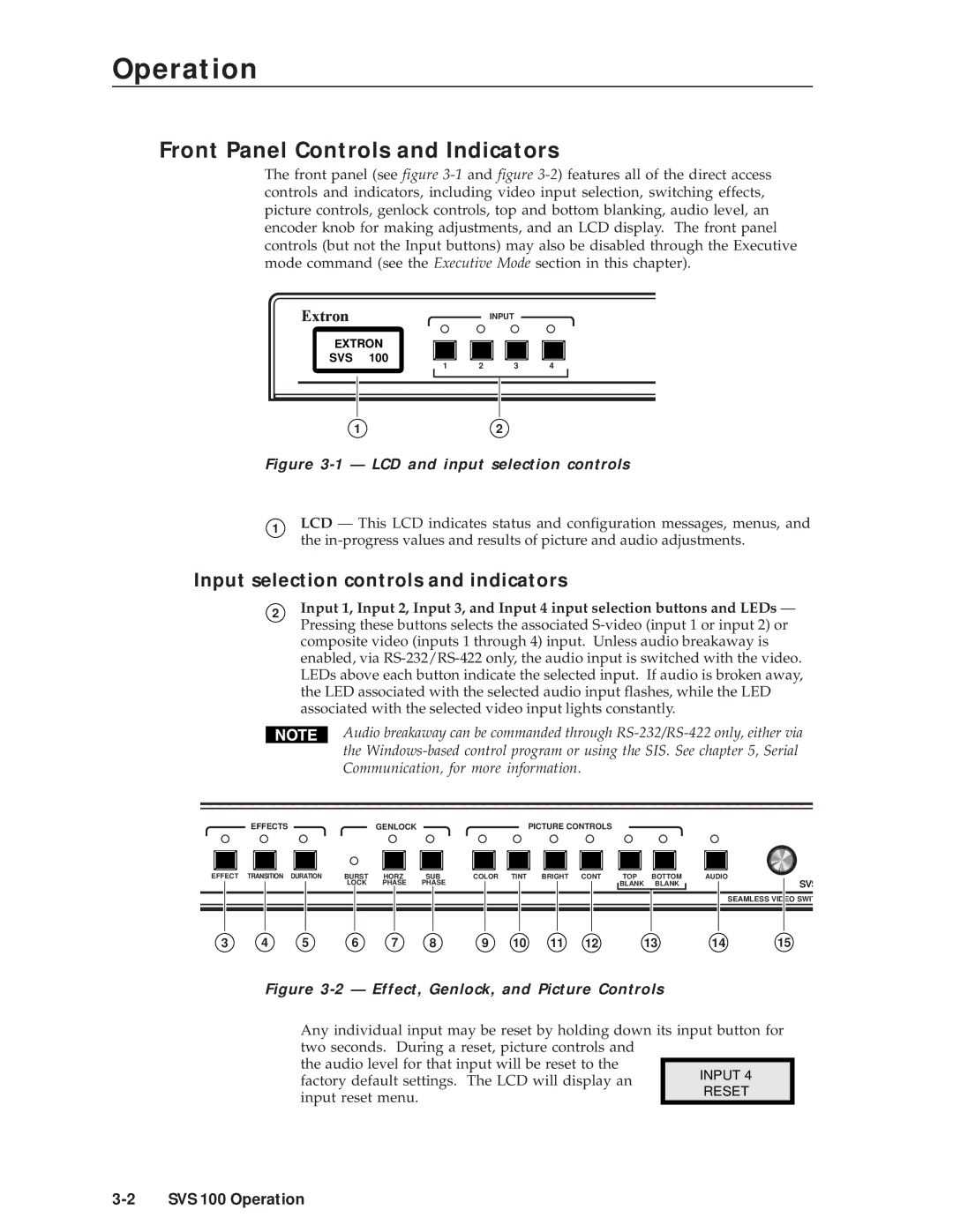
Figure 3-1 — LCD and input selection controls
1LCD — This LCD indicates status and configuration messages, menus, and the
Input selection controls and indicators
2Input 1, Input 2, Input 3, and Input 4 input selection buttons and LEDs — Pressing these buttons selects the associated
Audio breakaway can be commanded through
EFFECTS |
| GENLOCK |
| PICTURE CONTROLS |
|
|
|
EFFECT TRANSITION DURATION | BURST | HORZ | SUB | COLOR TINT BRIGHT CONT | TOP | BOTTOM | AUDIO |
| LOCK | PHASE | PHASE |
| BLANK | BLANK | SVS |
SEAMLESS VIDEO SWIT
3 | 4 | 5 | 6 | 7 | 8 | 9 | 10 | 11 | 12 | 13 | 14 | 15 |
Figure 3-2 — Effect, Genlock, and Picture Controls
Any individual input may be reset by holding down its input button for two seconds. During a reset, picture controls and
the audio level for that input will be reset to the factory default settings. The LCD will display an input reset menu.