Installation, cont’d
With this method there is no way to know if the signals are 180º out of phase. A delayed sweep on a
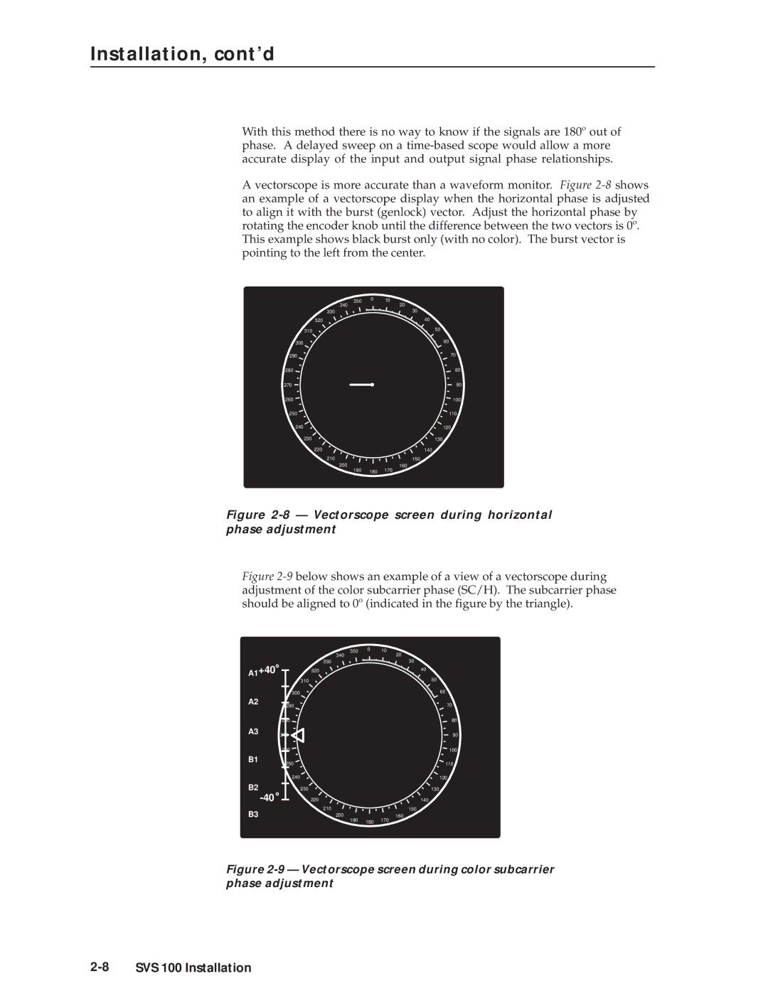
A vectorscope is more accurate than a waveform monitor. Figure
350 | 0 | 10 |
340 |
| 20 |
330 |
| 30 |
320 |
| 40 |
310 |
| 50 |
|
| |
300 |
| 60 |
290 |
| 70 |
280 |
| 80 |
270 |
| 90 |
260 |
| 100 |
250 |
| 110 |
240 |
| 120 |
230 |
| 130 |
220 |
| 140 |
210 |
| 150 |
200160
190 180 170
Figure 2-8 — Vectorscope screen during horizontal phase adjustment
Figure 2-9 below shows an example of a view of a vectorscope during adjustment of the color subcarrier phase (SC/H). The subcarrier phase should be aligned to 0º (indicated in the figure by the triangle).
350 | 0 | 10 |
340 |
| 20 |
330 |
| 30 |
A1+40 | 320 |
| 40 |
| 310 |
| 50 |
|
|
| |
| 300 |
| 60 |
|
|
| |
A2 | 290 |
| 70 |
|
| ||
| 280 |
| 80 |
A3 | 270 |
| 90 |
|
| ||
| 260 |
| 100 |
B1 | 250 |
| 110 |
|
| ||
| 240 |
| 120 |
B2 | 230 |
| 130 |
220 |
| 140 | |
B3 | 210 |
| 150 |
200 |
| 160 | |
| 190 | 180 | 170 |