Quick Start — SVS 100
Installation
Step 1
Turn off power to the SVS 100 and all other devices that will be connected.
two mounting screws on each side
![]() bracket
bracket
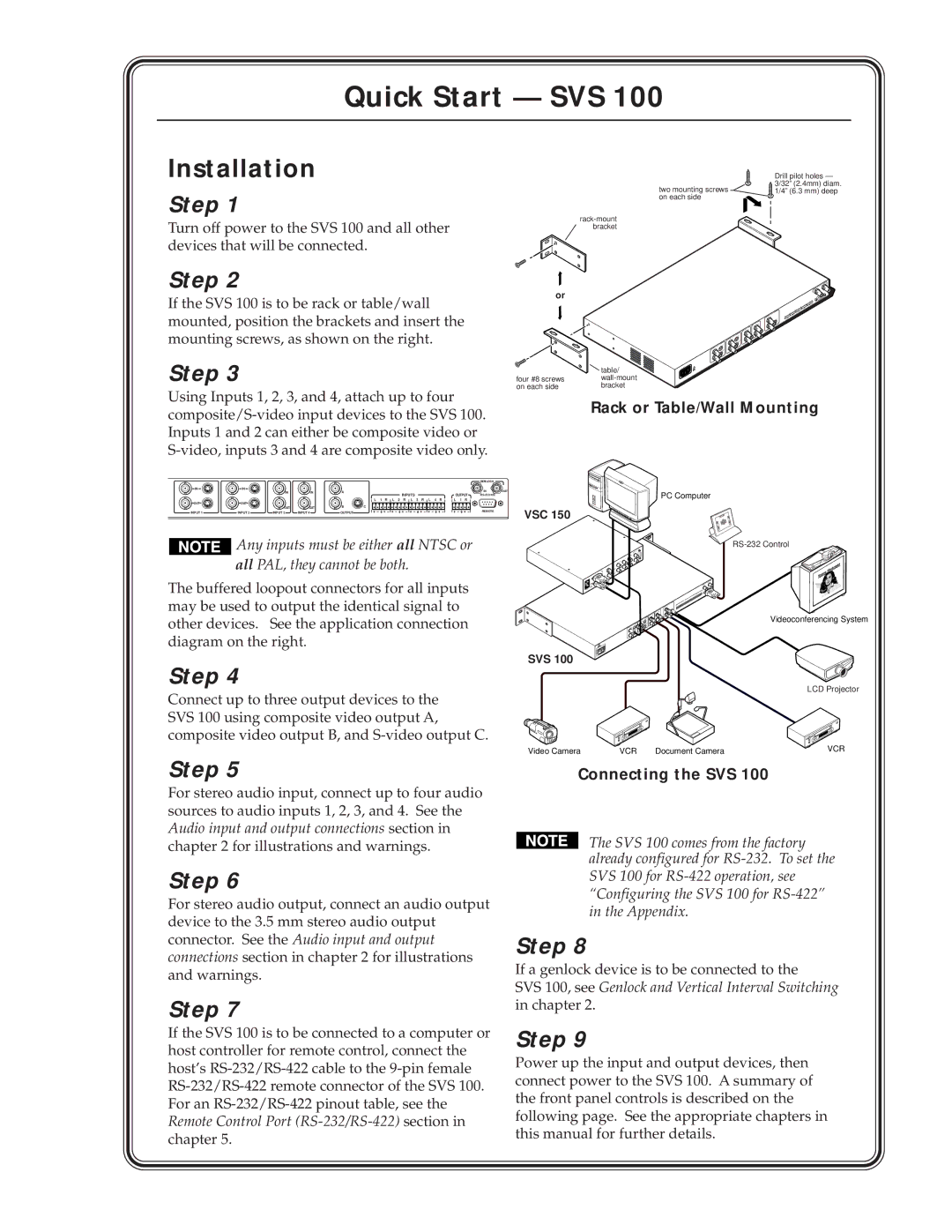
Drill pilot holes — 3/32” (2.4mm) diam. 1/4” (6.3 mm) deep
Step 2
If the SVS 100 is to be rack or table/wall mounted, position the brackets and insert the mounting screws, as shown on the right.
Step 3
Using Inputs 1, 2, 3, and 4, attach up to four
or
| table/ |
four #8 screws | |
on each side | bracket |
Rack or Table/Wall Mounting
|
|
|
|
|
|
| GENLOCK |
|
IN | IN |
|
|
|
|
| IN | OUT |
|
| IN | IN | A | INPUTS | OUTPUT | ||
|
|
|
|
|
| |||
OUT | OUT |
|
|
| L 1 R L 2 R L 3 R L 4 R | L 1 R |
|
|
|
|
|
|
|
|
| ||
|
| OUT | OUT | B | C |
|
|
|
INPUT 1 | INPUT 2 | INPUT 3 | INPUT 4 | OUTPUT |
|
| REMOTE |
|
![]()
![]()
![]()
![]()
![]() Any inputs must be either all NTSC or
Any inputs must be either all NTSC or
all PAL, they cannot be both.
The buffered loopout connectors for all inputs may be used to output the identical signal to other devices. See the application connection diagram on the right.
Step 4
Connect up to three output devices to the SVS 100 using composite video output A, composite video output B, and
Step 5
For stereo audio input, connect up to four audio sources to audio inputs 1, 2, 3, and 4. See the Audio input and output connections section in chapter 2 for illustrations and warnings.
Step 6
For stereo audio output, connect an audio output device to the 3.5 mm stereo audio output connector. See the Audio input and output connections section in chapter 2 for illustrations and warnings.
Step 7
If the SVS 100 is to be connected to a computer or host controller for remote control, connect the host’s
PC Computer
VSC 150
Videoconferencing System
SVS 100
LCD Projector
Video Camera | VCR | Document Camera | VCR |
Connecting the SVS 100
The SVS 100 comes from the factory already configured for
Step 8
If a genlock device is to be connected to the
SVS 100, see Genlock and Vertical Interval Switching in chapter 2.
Step 9
Power up the input and output devices, then connect power to the SVS 100. A summary of the front panel controls is described on the following page. See the appropriate chapters in this manual for further details.