32*30!
In this example, input #32 is being switched to output #30 (with audio following video)
3. The last SIS command to the SVS 100 will select an input:
1!
In this example, Input #1 is selected as the current input (with audio following video).
Configuring the SVS 100 for RS-422
The SVS 100 comes configured from the factory for
Removing the top cover
The top cover of the SVS 100 must first be removed to gain access to the ribbon cable and jumper.
1.Disconnect the power cord from the SVS 100.
2.If the SVS 100 is rack mounted, remove the SVS from the rack.
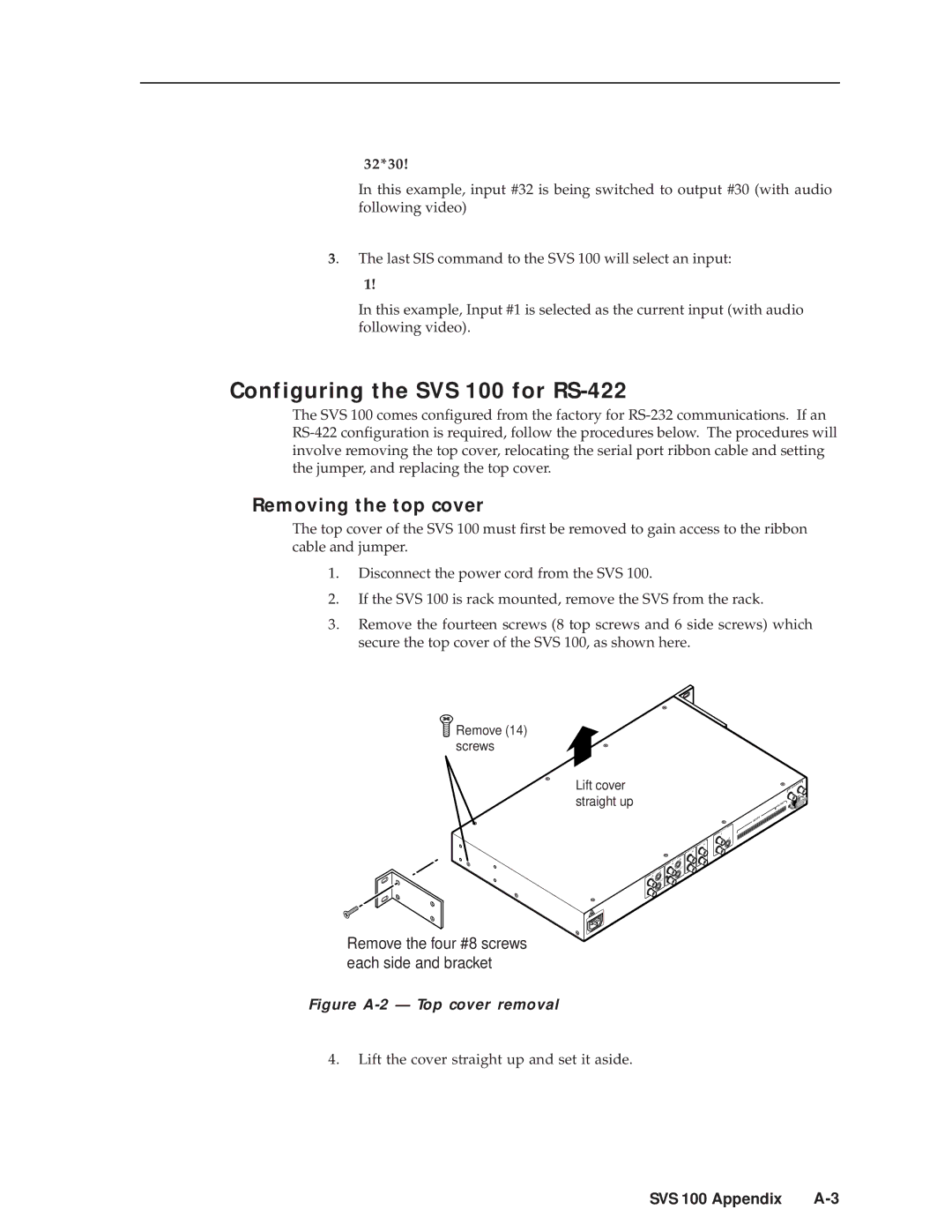
3.Remove the fourteen screws (8 top screws and 6 side screws) which secure the top cover of the SVS 100, as shown here.
 Remove (14) screws
Lift cover straight up
1 | IN |
INPUT |
|
IN |
|
| OUT |
OUT |
|
|
| 4 |
|
| INPUTIN |
|
| 3 |
|
| INPUTIN |
|
| OUT |
| 2 | IN |
INPUT | IN | |
| OUT | |
IN |
|
|
OUT
IN
OUT
OUT ![]()
OUTPUT
A
![]() A
A
B
![]() B
B
C
C
GENLOCK
OUT
IN
OUTPUT1 R | REMOTE |
L |
R 4 L
R
INPUTSL 3
R
2 L R 1 L
Remove the four #8 screws each side and bracket
Figure A-2 — Top cover removal
4.Lift the cover straight up and set it aside.
SVS 100 Appendix |