Reference Information, cont’d
Relocating the ribbon cable and setting the jumper
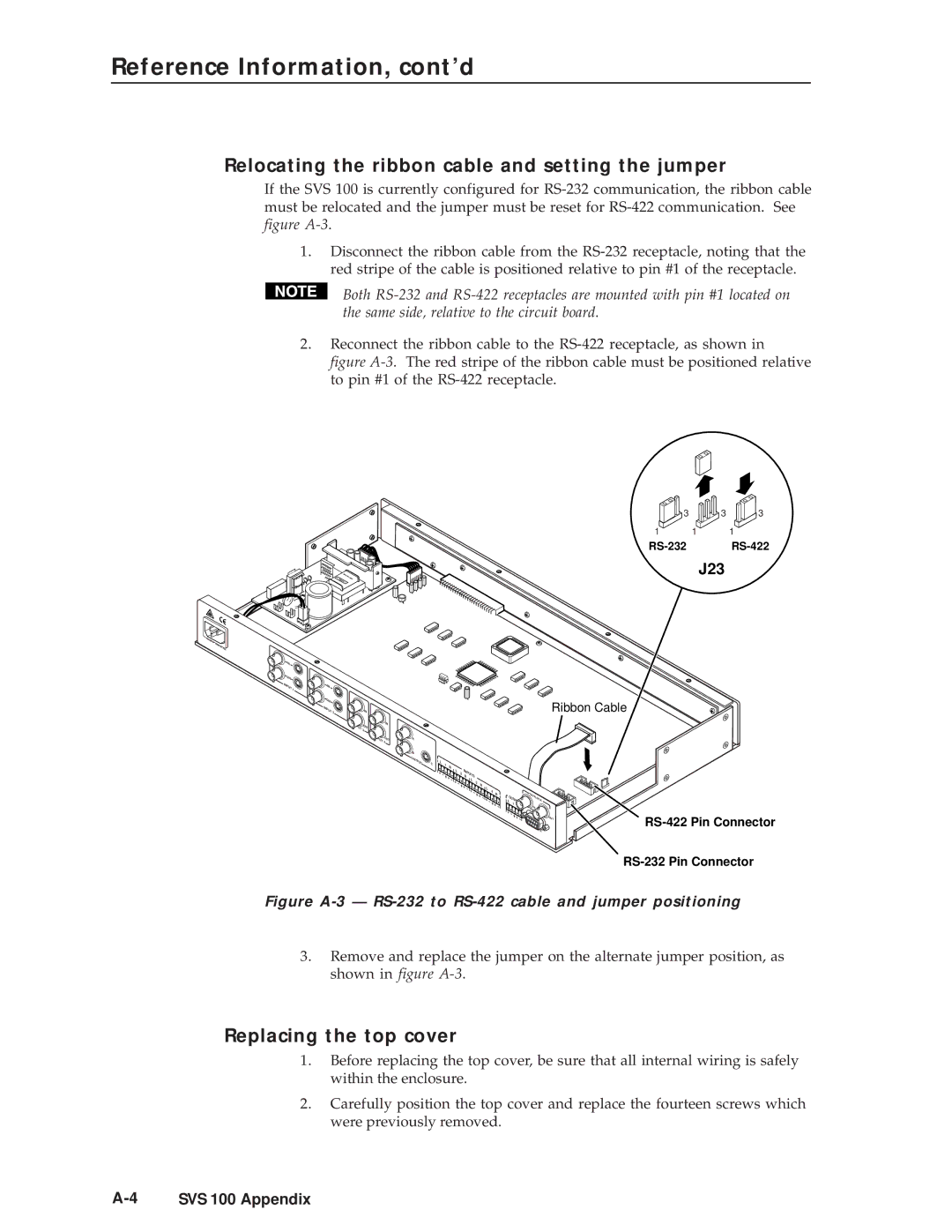
If the SVS 100 is currently configured for
1.Disconnect the ribbon cable from the
Both
2.Reconnect the ribbon cable to the
figure A-3. The red stripe of the ribbon cable must be positioned relative to pin #1 of the RS-422 receptacle.
3 | 3 | 3 |
1 | 1 | 1 |
J23
IN
![]()
![]() OUT INPUT 1
OUT INPUT 1
IN
![]() OUT
OUT
INPUT 2
![]() INPUT
INPUT
IN
OUT 3
![]() IN INPUT 4OUT
IN INPUT 4OUT
Ribbon Cable
A |
|
|
|
|
|
|
B |
|
|
|
|
|
|
OUTPUT | C | L | 1 |
|
|
|
|
|
|
| R |
| INPUTSR |
|
|
|
| L | 2 | |
|
|
|
|
|
|
L | 3 |
|
| R | |
|
|
L | 4 |
|
|
|
|
| R |
| GENLOCK |
| |
|
|
|
| ||
|
| LOUTPUT |
| ||
|
| 1 | R | IN |
|
|
|
|
| RS- |
|
|
|
|
| 232/422 | OUT |
|
|
|
|
| |
|
|
|
| REMOTE |
|
Figure A-3 — RS-232 to RS-422 cable and jumper positioning
3.Remove and replace the jumper on the alternate jumper position, as shown in figure
Replacing the top cover
1.Before replacing the top cover, be sure that all internal wiring is safely within the enclosure.
2.Carefully position the top cover and replace the fourteen screws which were previously removed.
