Installation, cont’d
6
A
L 1 R
BC
OUTPUT
INPUTS
L 2 R L 3 R
L 4 R
| GENLOCK |
|
| IN | OUT |
OUTPUT |
| |
L 1 R |
|
|
REMOTE
6 | 7 | 8 | 8 | 8 | 8 | 9 |
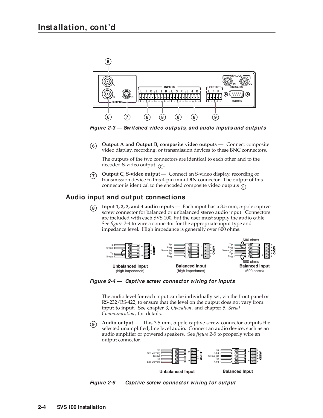
Figure 2-3 — Switched video outputs, and audio inputs and outputs
6
7
Output A and Output B, composite video outputs — Connect composite video display, recording, or transmission devices to these BNC connectors.
The outputs of the two connectors are identical to each other and to the decoded
Output C,
Audio input and output connections
8Input 1, 2, 3, and 4 audio inputs — Each input has a 3.5 mm,
See figure
Tip Sleeve
Tip Sleeve
Tip
Ring
Sleeve (s)
Tip
Ring
600 ohms
Tip
Ring
Sleeve (s)
Tip
Ring
|
| 600 ohms |
Unbalanced Input | Balanced Input | Balanced Input |
(high impedance) | (high impedance) | (600 ohms) |
Figure 2-4 — Captive screw connector wiring for inputs
The audio level for each input can be individually set, via the front panel or
9Audio output — This 3.5 mm,
Tip ![]() See warning
See warning ![]() Sleeve
Sleeve ![]() Tip
Tip ![]()
See warning ![]()
Tip
Ring
Sleeve (s)
Tip
Ring
Unbalanced Input | Balanced Input |