Rear Panel Connectors
1 | 2 | 3 |
|
| 4 |
|
| 5 |
| 6 |
|
| 7 |
| 8 |
|
| 9 | 10 |
|
|
|
| SW P 1 2 3- 2 |
|
| AUDIO | [VGA] |
|
|
| AU DIO [ S- VIDEO] |
|
| AUD IO [COMPO SITE] |
|
| 0.4A 50/60Hz | |||||||
|
|
|
|
|
|
|
|
|
|
|
|
|
|
|
|
|
|
| MASTER |
|
|
|
|
|
|
| L | L | L | L | OUTPUT | L | L | L | L | OUTPUT | L | L | L | L | OUTPUT | AUDIO |
|
|
|
| +24V | TALK OVER |
| OUTPUT |
|
| 11 | |||||||||||||||
|
|
|
|
|
| + |
|
|
|
| + |
|
|
|
| + | + |
|
| |||
| PHANTOM | THRESHOLD |
|
|
|
|
|
|
|
|
|
|
|
|
|
|
| |||||
| POWER | ADJUST |
|
|
|
|
| - R |
|
|
|
| - R |
|
|
|
| - R |
|
| ||
| OFF | + |
| R | R | R | R |
| R | R | R | R |
| R | R | R | R |
|
|
|
|
|
|
|
|
|
|
|
|
| - L |
|
|
|
| - L |
|
|
|
| - L | - L |
|
| 12 |
| ON |
| INPUT 1 | INPUT 2 | INPUT 3 | INPUT 4 | + | INPUT 1 | INPUT 2 | INPUT 3 | INPUT 4 | + | INPUT 1 | INPUT 2 | INPUT 3 | INPUT 4 | + | + |
|
| ||
MIC INPUT |
|
|
|
|
|
|
| |||||||||||||||
|
|
|
|
|
|
|
|
|
|
|
|
|
|
|
|
|
|
|
|
| ||
|
|
|
|
|
|
|
|
|
|
|
|
|
|
| MADE IN U. S. A . |
|
|
|
| FUSE: 1.6A 250V | ||
|
|
|
|
|
|
|
|
|
|
|
|
|
|
|
|
|
|
| TIME DELAY | |||
|
|
|
| VGA |
|
|
|
|
|
| S- VIDEO |
|
|
| COMPO SITE VIDEO |
| SERIAL | SERIAL |
| |||
INPUT 1 |
| INPUT 2 | INPUT 3 |
| INPUT 4 |
| OUTPUT | INPUT 1 | INPUT 2 | INPUT 3 | INPUT 4 | OUTPUT | INPUT 1 | INPUT 2 | INPUT 3 | INPUT 4 | OUTPUT | PORT | L I ST E D | |||
|
|
|
|
|
|
|
|
| FORMAT C | 1 T 2 3 | ||||||||||||
|
|
|
|
|
|
|
|
|
|
|
|
|
|
|
|
|
|
| R X + SELECT | I . T. E . | ||
|
|
|
|
|
|
|
|
|
|
|
|
|
|
|
|
|
|
| R X - |
|
|
|
|
|
|
|
|
|
|
|
|
|
|
|
|
|
|
|
|
|
| T X + |
|
|
|
|
|
|
|
|
|
|
|
|
|
|
|
|
|
|
|
|
|
| T X - |
|
| MADE IN |
|
|
|
|
|
|
|
|
|
|
|
|
|
|
|
|
|
|
| G N D |
|
| |
|
|
|
|
|
|
|
|
|
|
|
|
|
|
|
|
|
|
|
|
|
| USA |
|
|
|
|
|
|
|
|
|
|
|
|
|
|
|
|
|
|
| R S2 32 | R S4 2 2 / 4 8 5 | ||
|
|
| 20 |
|
|
|
| 19 |
| 18 |
| 17 |
| 16 |
| 15 | 14 | 13 |
| |||
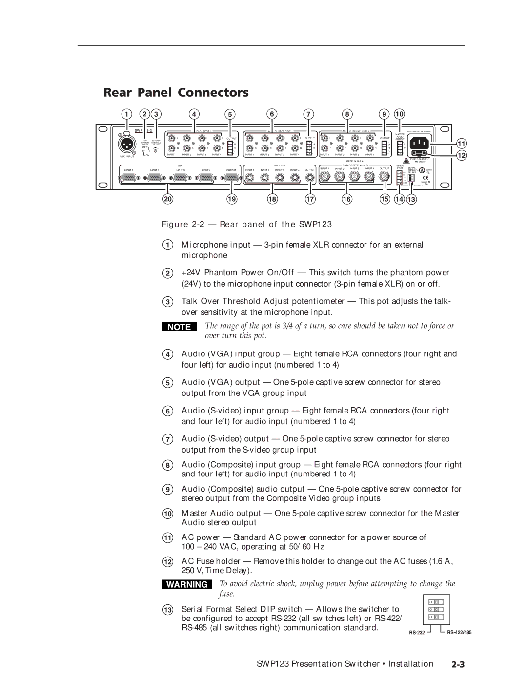
Figure 2-2 — Rear panel of the SWP123
1Microphone input —
2+24V Phantom Power On/Off — This switch turns the phantom power (24V) to the microphone input connector
3Talk Over Threshold Adjust potentiometer — This pot adjusts the talk- over sensitivity at the microphone input.
The range of the pot is 3/4 of a turn, so care should be taken not to force or over turn this pot.
4Audio (VGA) input group — Eight female RCA connectors (four right and four left) for audio input (numbered 1 to 4)
5Audio (VGA) output — One
6Audio
7Audio
8
9
Audio (Composite) input group — Eight female RCA connectors (four right and four left) for audio input (numbered 1 to 4)
Audio (Composite) audio output — One
10Master Audio output — One
11AC power — Standard AC power connector for a power source of 100 – 240 VAC, operating at 50/60 Hz
12AC Fuse holder — Remove this holder to change out the AC fuses (1.6 A, 250 V, Time Delay).
To avoid electric shock, unplug power before attempting to change the fuse.
13 Serial Format Select DIP switch — Allows the switcher to be configured to accept
SWP123 Presentation Switcher • Installation |