Installation, cont’d
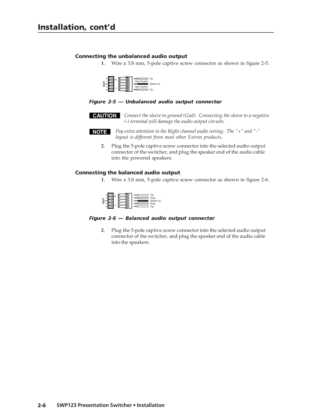
Connecting the unbalanced audio output
1. Wire a 3.8 mm,
OUT L R
Tip
See Caution
Sleeve (s)
See Caution
Tip
Figure 2-5 — Unbalanced audio output connector
CAUTION
Connect the sleeve to ground (Gnd). Connecting the sleeve to a negative
Pay extra attention to the Right channel audio wiring. The “+” and
2. Plug the
Connecting the balanced audio output
1. Wire a 3.8 mm,
OUT L R
Tip
Ring
Sleeve (s)
Ring
Tip
Figure 2-6 — Balanced audio output connector
2. Plug the