Installation, cont’d
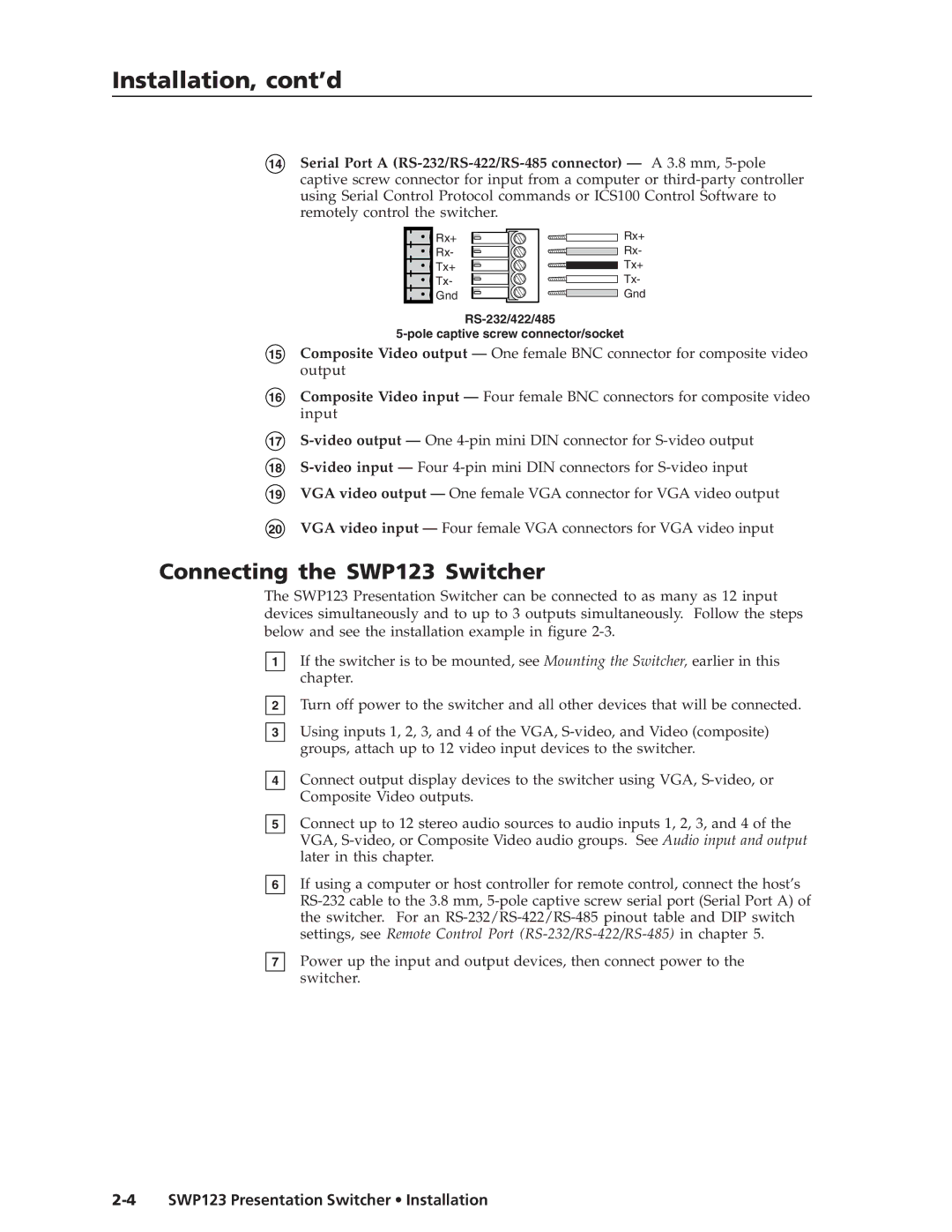
14Serial Port A
Rx+
Rx-
Tx+
Tx-
Gnd
Rx+
Rx-
Tx+
Tx-
Gnd
15Composite Video output — One female BNC connector for composite video output
16Composite Video input — Four female BNC connectors for composite video input
17
18
19VGA video output — One female VGA connector for VGA video output
20VGA video input — Four female VGA connectors for VGA video input
Connecting the SWP123 Switcher
The SWP123 Presentation Switcher can be connected to as many as 12 input devices simultaneously and to up to 3 outputs simultaneously. Follow the steps below and see the installation example in figure
1
2
3
4
5
6
7
If the switcher is to be mounted, see Mounting the Switcher, earlier in this chapter.
Turn off power to the switcher and all other devices that will be connected.
Using inputs 1, 2, 3, and 4 of the VGA,
Connect output display devices to the switcher using VGA,
Connect up to 12 stereo audio sources to audio inputs 1, 2, 3, and 4 of the VGA,
If using a computer or host controller for remote control, connect the host’s
Power up the input and output devices, then connect power to the switcher.