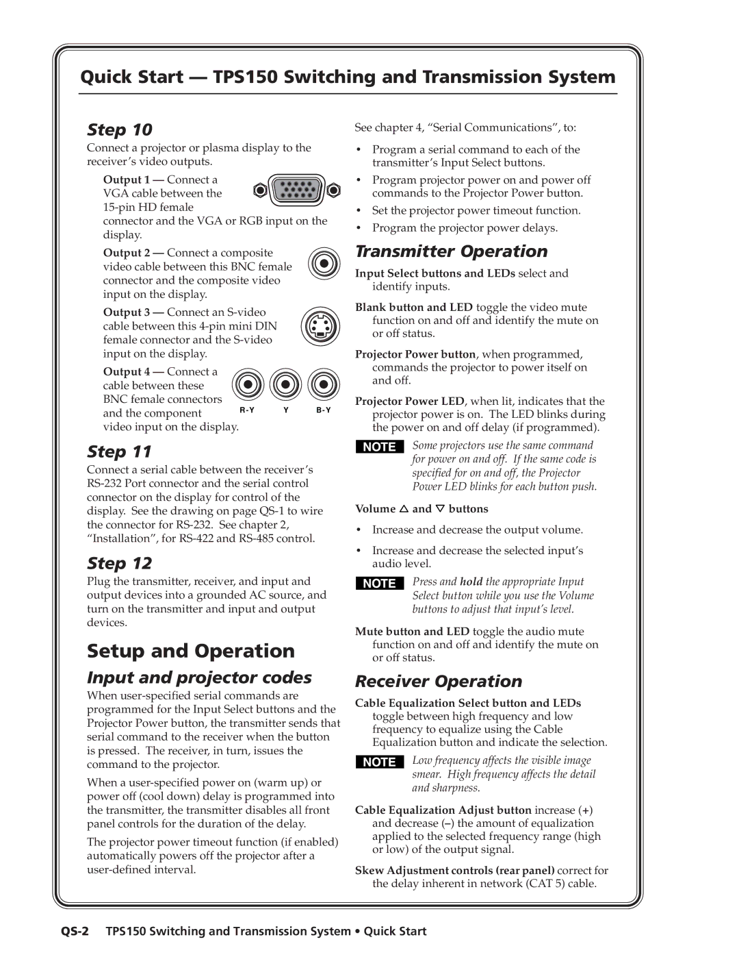
TPS150 specifications
The Extron TPS150 is a highly regarded touch panel system designed for professional AV environments, providing an intuitive interface for controlling various audio and video components. This device is part of Extron's popular TouchLink Pro series, which is known for its robustness and versatility in managing classroom and conference room technology.One of the standout features of the TPS150 is its high-resolution capacitive touch screen, which measures at 15 inches. This screen delivers vibrant colors and exceptional clarity, ensuring that users can easily interact with the device even in well-lit environments. The touch panel's interface is fully customizable, allowing users to create a layout tailored to their specific needs. This customization can include the addition of buttons, sliders, and dynamic graphics that make navigation seamless and user-friendly.
In terms of connectivity, the TPS150 supports Ethernet communication, which enables easy integration with networked AV systems. This feature allows for remote access and control, making it easier for IT professionals to monitor and manage AV devices from a centralized location. Additionally, the TPS150 is compatible with various Extron control systems, providing a robust platform for managing complex multimedia setups.
The device also incorporates advanced security features, ensuring that sensitive system controls are protected from unauthorized access. Administrators can establish user permissions and authentication processes to maintain control over the AV environment, which is particularly important in corporate and educational settings.
Moreover, the TPS150 supports Extron's global configurator software, which simplifies the setup process and allows for easy programming of touch panel interfaces. Users can design custom layouts quickly and efficiently, and the software also provides an extensive library of drivers for popular AV equipment, enhancing compatibility and functionality.
With its elegant design, high-quality components, and customizable interface, the Extron TPS150 touch panel offers an effective solution for AV control. Whether used in educational, corporate, or professional environments, it empowers users to streamline their audiovisual experiences and maintain effective control over their technology, ensuring successful presentations and meetings.

