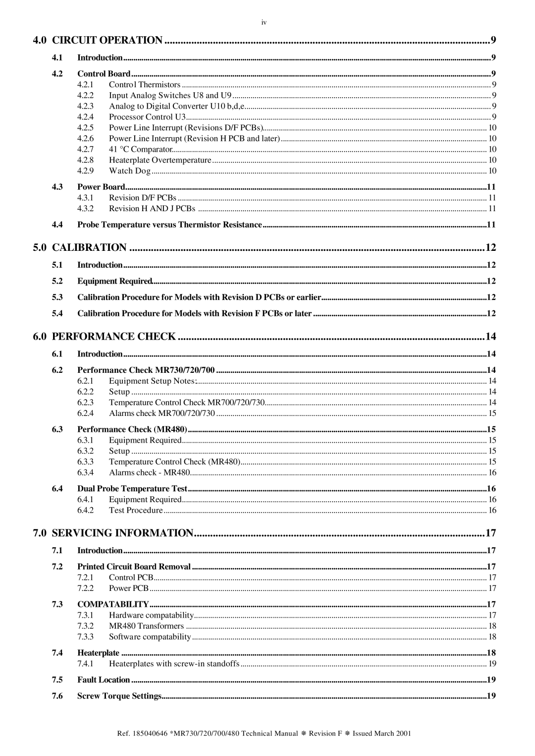
|
| iv |
|
4.0 CIRCUIT OPERATION | 9 | ||
4.1 | Introduction | 9 | |
4.2 | Control Board | 9 | |
| 4.2.1 | Control Thermistors | 9 |
| 4.2.2 | Input Analog Switches U8 and U9 | 9 |
| 4.2.3 | Analog to Digital Converter U10 b,d,e | 9 |
| 4.2.4 | Processor Control U3 | 9 |
| 4.2.5 | Power Line Interrupt (Revisions D/F PCBs) | 10 |
| 4.2.6 | Power Line Interrupt (Revision H PCB and later) | 10 |
| 4.2.7 | 41 °C Comparator | 10 |
| 4.2.8 | Heaterplate Overtemperature | 10 |
| 4.2.9 | Watch Dog | 10 |
4.3 | Power Board | 11 | |
| 4.3.1 | Revision D/F PCBs | 11 |
| 4.3.2 | Revision H AND J PCBs | 11 |
4.4 | Probe Temperature versus Thermistor Resistance | 11 | |
5.0 CALIBRATION | 12 | ||
5.1 | Introduction | 12 | |
5.2 | Equipment Required | 12 | |
5.3 | Calibration Procedure for Models with Revision D PCBs or earlier | 12 | |
5.4 | Calibration Procedure for Models with Revision F PCBs or later | 12 | |
6.0 PERFORMANCE CHECK | 14 | ||
6.1 | Introduction | 14 | |
6.2 | Performance Check MR730/720/700 | 14 | |
| 6.2.1 | Equipment Setup Notes: | 14 |
| 6.2.2 | Setup | 14 |
| 6.2.3 | Temperature Control Check MR700/720/730 | 14 |
| 6.2.4 | Alarms check MR700/720/730 | 15 |
6.3 | Performance Check (MR480) | 15 | |
| 6.3.1 | Equipment Required | 15 |
| 6.3.2 | Setup | 15 |
| 6.3.3 | Temperature Control Check (MR480) | 15 |
| 6.3.4 | Alarms check - MR480 | 16 |
6.4 | Dual Probe Temperature Test | 16 | |
| 6.4.1 | Equipment Required | 16 |
| 6.4.2 | Test Procedure | 16 |
7.0 SERVICING INFORMATION | 17 | ||
7.1 | Introduction | 17 | |
7.2 | Printed Circuit Board Removal | 17 | |
| 7.2.1 | Control PCB | 17 |
| 7.2.2 | Power PCB | 17 |
7.3 | COMPATABILITY | 17 | |
| 7.3.1 | Hardware compatability | 17 |
| 7.3.2 | MR480 Transformers | 18 |
| 7.3.3 | Software compatability | 18 |
7.4 | Heaterplate | 18 | |
| 7.4.1 | Heaterplates with | 19 |
7.5 | Fault Location | 19 | |
7.6 | Screw Torque Settings | 19 | |
Ref. 185040646 *MR730/720/700/480 Technical Manual ¯ Revision F ¯ Issued March 2001
