46
The data record as received should start with an ‘:’ and end with an ‘LF’. Under abnormal operating conditions however (when there are ‘E’ messages in the display) some or all of the above packets ‘a’ to ‘g’ can be missing. The status information packet ‘h’ will always be present (as long as the micro is running) and will show the error condition.
When there are error messages in the display, bit 6 of the last status byte will be set high indicating a fatal error condition.
First Byte |
|
|
| |
Bit0 | Probe disconnect LED |
|
|
|
Bit1 | Heater Wire disconnect LED |
|
|
|
Bit2 | Airway Temp Low LED |
|
|
|
Bit3 | Airway Temp High LED |
|
|
|
Bit4 | Chamber Temp Low LED |
|
|
|
Bit5 | Chamber Temp High LED |
|
|
|
Bit6 | Chamber Temp Button LED |
|
|
|
Bit7 | Always set high |
|
|
|
Second Byte |
|
|
| |
Bit0 | Standby button LED |
|
|
|
Bit1 | Heater Wire operation LED |
|
|
|
Bit2 | Remote Shut Down request acknowledge |
|
| |
Bit3 | Set Low LED |
|
|
|
Bit4 | Audio alarm muted |
|
|
|
Bit5 | External request acknowledge Heater Wire operation |
| ||
Bit6 | External request acknowledge No Heater Wire operation |
| ||
Bit7 | Always set high |
|
|
|
Third Byte |
|
|
| |
Bit0 | Heaterplate ON |
|
|
|
Bit1 | Heater Wire ON |
|
|
|
Bit2 | Always low |
|
|
|
|
|
|
|
|
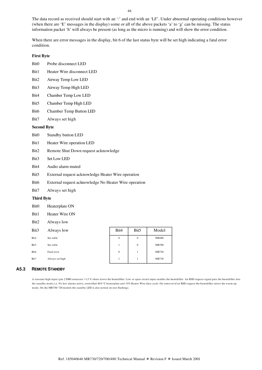
Bit3 | Always low | Bit4 | Bit5 | Model |
Bit4 | See table |
|
|
|
0 | 0 | MR480 | ||
Bit5 | See table | 1 | 0 | MR700 |
Bit6 | Fatal error | 0 | 1 | MR720 |
Bit7 | Always set high | 1 | 1 | MR730 |
|
|
|
|
|
A5.3 REMOTE STANDBY
A constant high input (pin 2 DB9 connector >1.5 V) shuts down the humidifier. Low or open circuit input enables the humidifier. An RSD request signal puts the humidifier into the standby mode; i.e. No low alarms active, controlled 40.0 °C heaterplate and 15% Heater Wire duty cycle. On removal of an RSD request the humidifier enters the warm up mode. On the MR730/720 models the standby LED is also turned on (not flashing).
Ref. 185040646 MR730/720/700/480 Technical Manual ¯ Revision F ¯ Issued March 2001