54
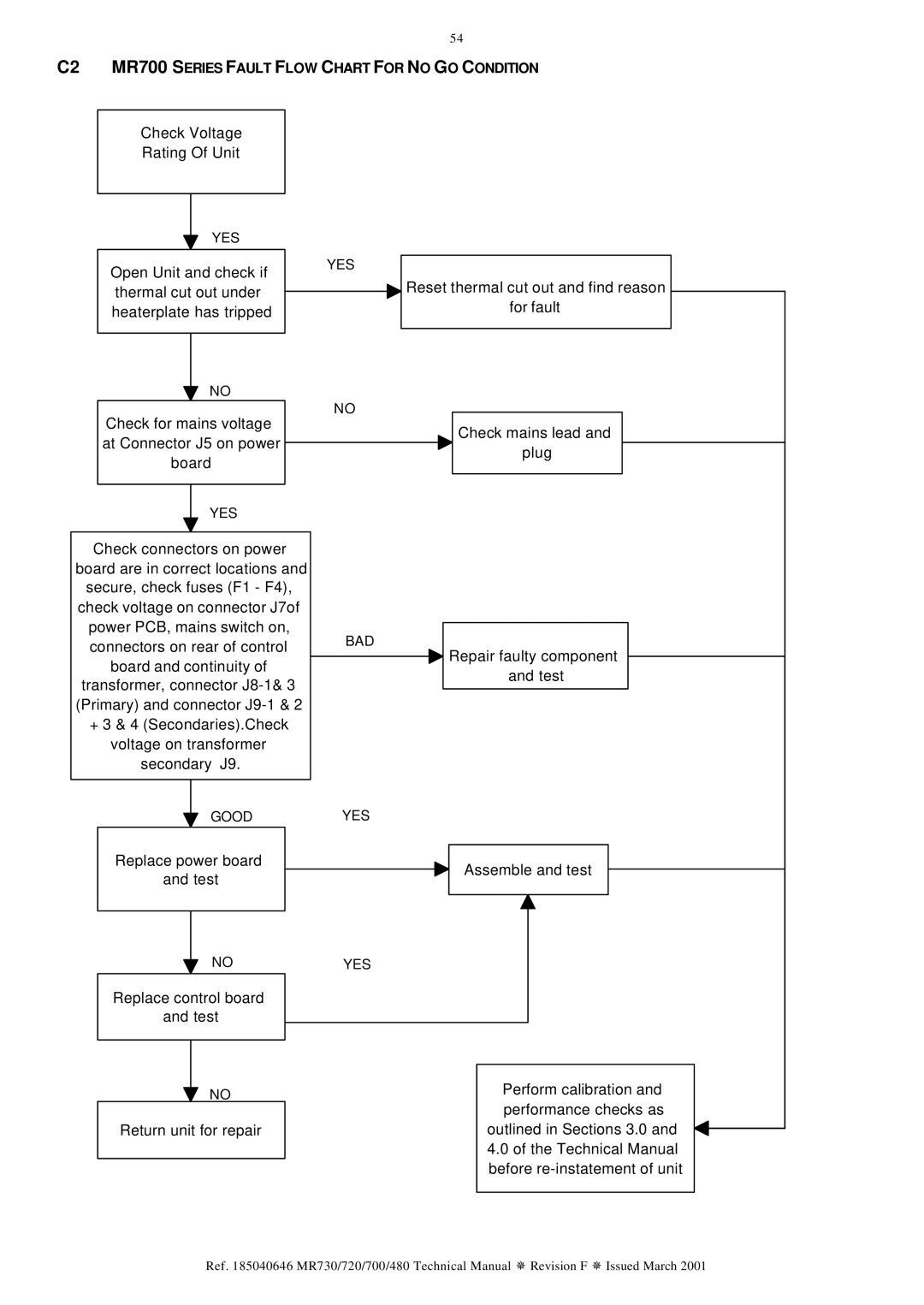
C2 MR700 SERIES FAULT FLOW CHART FOR NO GO CONDITION
Check Voltage
Rating Of Unit
YES
Open Unit and check if thermal cut out under heaterplate has tripped
NO
Check for mains voltage at Connector J5 on power board
YES
![]() Reset thermal cut out and find reason for fault
Reset thermal cut out and find reason for fault
NO
Check mains lead and plug
YES
Check connectors on power board are in correct locations and secure, check fuses (F1 - F4), check voltage on connector J7of power PCB, mains switch on, connectors on rear of control board and continuity of transformer, connector
+3 & 4 (Secondaries).Check voltage on transformer
secondary J9.
BAD
![]() Repair faulty component and test
Repair faulty component and test
GOOD
Replace power board and test
NO
Replace control board and test
NO
Return unit for repair
YES
Assemble and test
YES
Perform calibration and performance checks as outlined in Sections 3.0 and
4.0of the Technical Manual before
Ref. 185040646 MR730/720/700/480 Technical Manual ¯ Revision F ¯ Issued March 2001