80 Series V
Calibration Manual
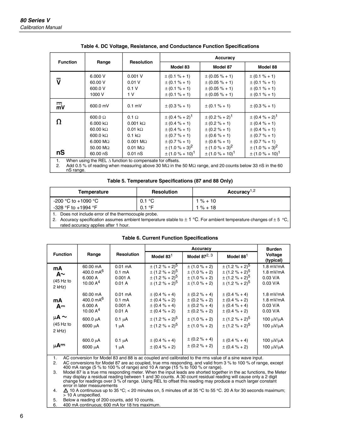
Table 4. DC Voltage, Resistance, and Conductance Function Specifications
Function | Range | Resolution |
| Accuracy |
| ||
Model 83 | Model 87 | Model 88 | |||||
|
|
|
| ||||
|
|
|
|
|
|
| |
L | 6.000 | V | 0.001 V | ± (0.1 % + 1) | ± (0.05 % + 1) | ± (0.1 % + 1) | |
60.00 | V | 0.01 V | ± (0.1 % + 1) | ± (0.05 % + 1) | ± (0.1 % + 1) | ||
| 600.0 | V | 0.1 V | ± (0.1 % + 1) | ± (0.05 % + 1) | ± (0.1 % + 1) | |
| 1000 V | 1 V | ± (0.1 % + 1) | ± (0.05 % + 1) | ± (0.1 % + 1) | ||
|
|
|
|
|
|
| |
F | 600.0 mV | 0.1 mV | ± (0.3 % + 1) | ± (0.1 % + 1) | ± (0.3 % + 1) | ||
mV | |||||||
e | 600.0 | Ω | 0.1 Ω | ± (0.4 % + 2)1 | ± (0.2 % + 2)1 | ± (0.4 % + 2)1 | |
6.000 kΩ | 0.001 kΩ | ± (0.4 % + 1) | ± (0.2 % + 1) | ± (0.4 % + 1) | |||
| 60.00 kΩ | 0.01 kΩ | ± (0.4 % + 1) | ± (0.2 % + 1) | ± (0.4 % + 1) | ||
| 600.0 kΩ | 0.1 kΩ | ± (0.7 % + 1) | ± (0.6 % + 1) | ± (0.7 % + 1) | ||
| 6.000 | MΩ | 0.001 MΩ | ± (0.7 % + 1) | ± (0.6 % + 1) | ± (0.7 % + 1) | |
nS | 50.00 | MΩ | 0.01 MΩ | ± (1.0 % + 3)2 | ± (1.0 % + 3)2 | ± (1.0 % + 3)2 | |
60.00 nS | 0.01 nS | ± (1.0 % + 10)1 | ± (1.0 % + 10)1 | ± (1.0 % + 10)1 | |||
1. When using the REL ∆ function to compensate for offsets.
2. Add 0.5 % of reading when measuring above 30 MΩ in the 50 MΩ range, and 20 counts below 33 nS in the 60 nS range.
Table 5. Temperature Specifications (87 and 88 Only)
|
| Temperature |
| Resolution | Accuracy1,2 |
| °C to +1090 °C | 0.1 | °C | 1 % + 10 | |
| °F to +1994 °F | 0.1 | °F | 1 % + 18 | |
1. | Does not include error of the thermocouple probe. |
| |||
2. | Accuracy specification assumes ambient temperature stable to ± 1 °C. For ambient temperature changes of ± 5 °C, | ||||
rated accuracy applies after 1 hour.
Table 6. Current Function Specifications
Function | Range | Resolution |
| Accuracy |
| Burden | |||
Model 831 | Model 872, 3 | Model 881 | Voltage | ||||||
|
|
|
|
|
|
|
| (typical) | |
mA |
| 60.00 mA | 0.01 mA | ± (1.2 % + 2)5 | ± (1.0 % + 2) | ± (1.2 % + 2)5 | 1.8 mV/mA | ||
\ | 400.0 mA6 | 0.1 mA | ± (1.2 % + 2)5 | ± (1.0 % + 2) | ± (1.2 % + 2)5 | 1.8 mV/mA | |||
6.000 | A | 0.001 A | ± (1.2 % + 2)5 | ± (1.0 % + 2) | ± (1.2 % + 2)5 | 0.03 V/A | |||
(45 Hz to | |||||||||
10.00 | A4 | 0.01 A | ± (1.2 % + 2)5 | ± (1.0 % + 2) | ± (1.2 % + 2)5 | 0.03 V/A | |||
2 kHz) |
|
|
|
|
|
|
| ||
|
| 60.00 mA | 0.01 mA | ± (0.4 % + 4) | ± (0.2 % + 4) | ± (0.4 % + 4) | 1.8 mV/mA | ||
mA |
| 400.0 mA6 | 0.1 mA | ± (0.4 % + 2) | ± (0.2 % + 2) | ± (0.4 % + 2) | 1.8 mV/mA | ||
[ | 6.000 | A | 0.001 A | ± (0.4 % + 4) | ± (0.2 % + 4) | ± (0.4 % + 4) | 0.03 V/A | ||
∝A B | 10.00 | A4 | 0.01 A | ± (0.4 % + 2) | ± (0.2 % + 2) | ± (0.4 % + 2) | 0.03 V/A | ||
600.0 | ∝A | 0.1 ∝A | ± (1.2 % + 2)5 | ± (1.0 % + 2) | ± (1.2 % + 2)5 | 100 ∝V/∝A | |||
(45 Hz to | 6000 ∝A | 1 ∝A | ± (1.2 % + 2)5 | ± (1.0 % + 2) | ± (1.2 % + 2)5 | 100 ∝V/∝A | |||
2 kHz) |
|
|
|
|
|
|
| ||
∝AF | 600.0 | ∝A | 0.1 ∝A | ± (0.4 % + 4) | ± (0.2 % + 4) | ± (0.4 % + 4) | 100 ∝V/∝A | ||
6000 ∝A | 1 ∝A | ± (0.4 % + 2) | ± (0.2 % + 2) | ± (0.4 % + 2) | 100 ∝V/∝A | ||||
|
|
|
|
|
|
|
| ||
1. | AC conversion for Model 83 and 88 is ac coupled and calibrated to the rms value of a sine wave input. | ||||||||
2. | AC conversions for Model 87 are ac coupled, true rms responding, and valid from 3 % to 100 % of range, except | ||||||||
| 400 mA range (5 % to 100 % of range) and 10 A range (15 % to 100 % or range). |
| |||||||
3. | Model 87 is a true rms responding meter. When the input leads are shorted together in the ac functions, the Meter | ||||||||
| may display a residual reading between 1 and 30 counts. A 30 count residual reading will cause only a 2 digit | ||||||||
| change for readings over 3 % of range. Using REL to offset this reading may produce a much larger constant | ||||||||
| error in later measurements |
|
|
|
| ||||
4. | W 10 A continuous up to 35 °C; < 20 minutes on, 5 minutes off at 35 °C to 55 °C. 20 A for 30 seconds maximum; | ||||||||
| > 10 A unspecified. |
|
|
|
|
| |||
5. | Below a reading of 200 counts, add 10 counts. |
|
|
| |||||
6. | 400 mA continuous; 600 mA for 18 hrs maximum. |
|
|
| |||||
6