80 Series V
Calibration Manual
|
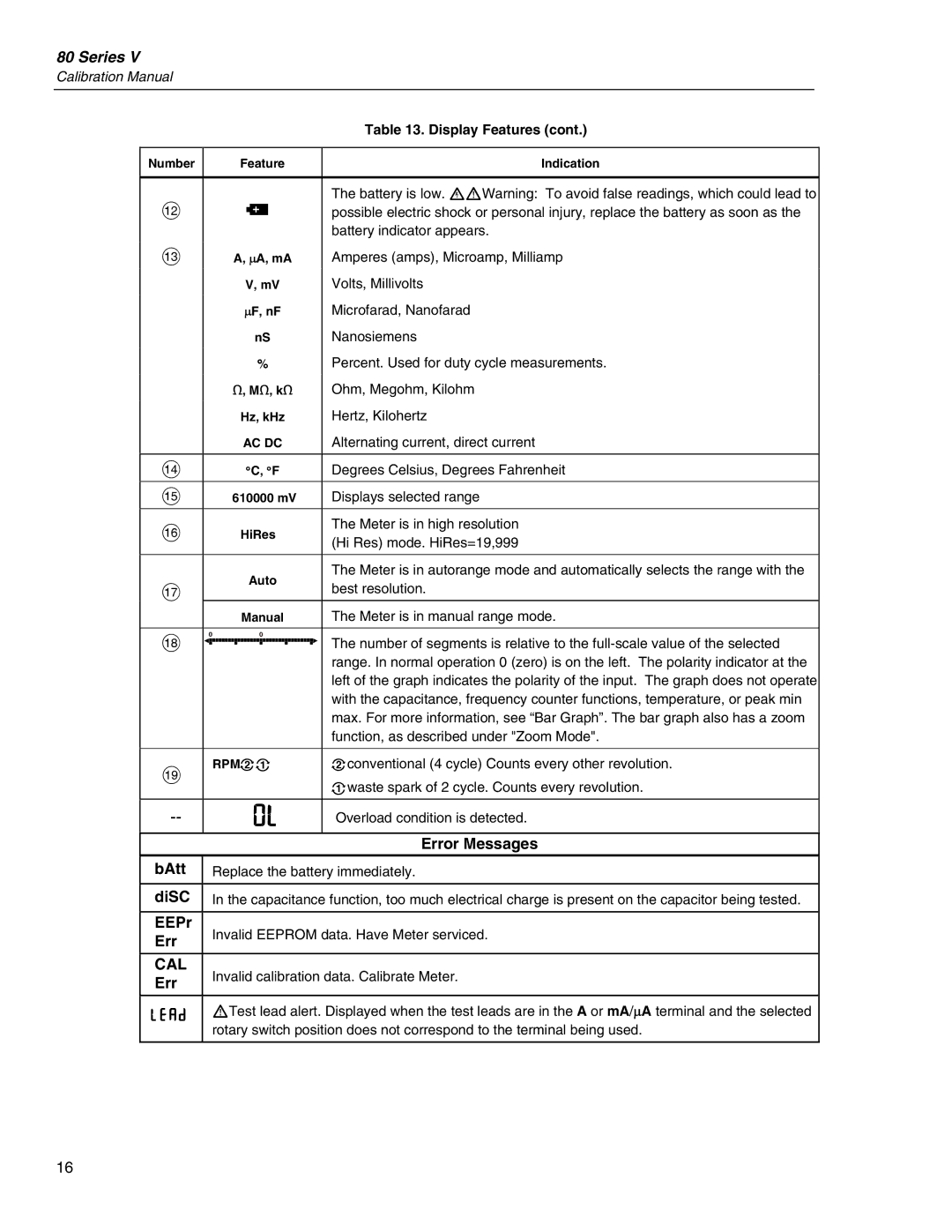
| Table 13. Display Features (cont.) | |
|
|
| |
Number | Feature | Indication | |
|
|
| |
|
| The battery is low. XWWarning: To avoid false readings, which could lead to | |
L | b | possible electric shock or personal injury, replace the battery as soon as the | |
|
| battery indicator appears. | |
M | A, ∝A, mA | Amperes (amps), Microamp, Milliamp | |
| V, mV | Volts, Millivolts | |
| ∝F, nF | Microfarad, Nanofarad | |
| nS | Nanosiemens | |
| % | Percent. Used for duty cycle measurements. | |
| e, Me, ke | Ohm, Megohm, Kilohm | |
| Hz, kHz | Hertz, Kilohertz | |
| AC DC | Alternating current, direct current | |
|
|
| |
N | °C, °F | Degrees Celsius, Degrees Fahrenheit | |
|
|
| |
O | 610000 mV | Displays selected range | |
|
|
| |
P | HiRes | The Meter is in high resolution | |
(Hi Res) mode. HiRes=19,999 | |||
|
| ||
|
|
| |
| Auto | The Meter is in autorange mode and automatically selects the range with the | |
Q | best resolution. | ||
| |||
| Manual | The Meter is in manual range mode. | |
|
|
| |
R |
| The number of segments is relative to the | |
|
| range. In normal operation 0 (zero) is on the left. The polarity indicator at the | |
|
| left of the graph indicates the polarity of the input. The graph does not operate | |
|
| with the capacitance, frequency counter functions, temperature, or peak min | |
|
| max. For more information, see “Bar Graph”. The bar graph also has a zoom | |
|
| function, as described under "Zoom Mode". | |
|
|
| |
S | RPMon | oconventional (4 cycle) Counts every other revolution. | |
|
| nwaste spark of 2 cycle. Counts every revolution. | |
0L | Overload condition is detected. | ||
|
|
| |
|
| Error Messages | |
bAtt | Replace the battery immediately. | ||
|
| ||
diSC | In the capacitance function, too much electrical charge is present on the capacitor being tested. | ||
|
|
| |
EEPr | Invalid EEPROM data. Have Meter serviced. | ||
Err | |||
|
| ||
|
|
| |
CAL | Invalid calibration data. Calibrate Meter. | ||
Err | |||
|
| ||
|
| ||
LEAd | WTest lead alert. Displayed when the test leads are in the A or mA/∝A terminal and the selected | ||
| rotary switch position does not correspond to the terminal being used. | ||
16
