Digital Multimeter
Specifications
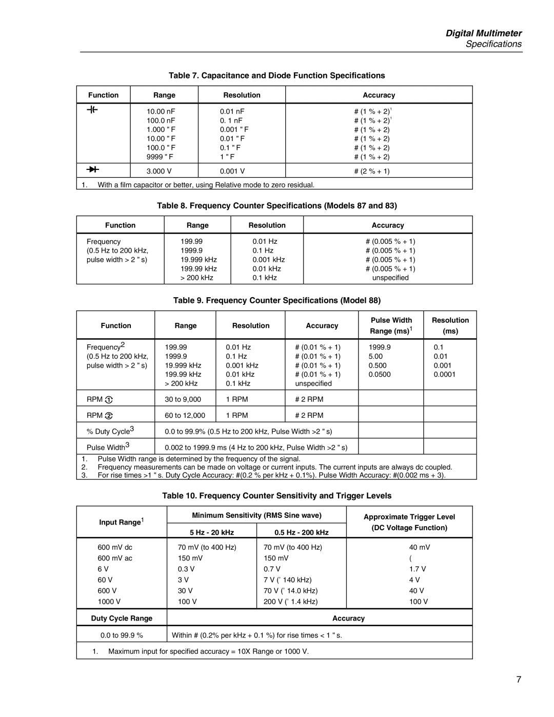
Table 7. Capacitance and Diode Function Specifications
Function | Range | Resolution | Accuracy | |
|
|
|
| |
E | 10.00 nF | 0.01 nF | ± (1 % + 2)1 | |
| 100.0 nF | 0. 1 nF | ± (1 % + 2)1 | |
| 1.000 | ∝F | 0.001 ∝F | ± (1 % + 2) |
| 10.00 | ∝F | 0.01 ∝F | ± (1 % + 2) |
| 100.0 | ∝F | 0.1 ∝F | ± (1 % + 2) |
| 9999 ∝F | 1 ∝F | ± (1 % + 2) | |
|
|
|
|
|
G | 3.000 | V | 0.001 V | ± (2 % + 1) |
|
|
|
|
|
1. With a film capacitor or better, using Relative mode to zero residual.
Table 8. Frequency Counter Specifications (Models 87 and 83)
Function | Range | Resolution | Accuracy |
|
|
|
|
Frequency | 199.99 | 0.01 Hz | ± (0.005 % + 1) |
(0.5 Hz to 200 kHz, | 1999.9 | 0.1 Hz | ± (0.005 % + 1) |
pulse width > 2 ∝s) | 19.999 kHz | 0.001 kHz | ± (0.005 % + 1) |
| 199.99 kHz | 0.01 kHz | ± (0.005 % + 1) |
| > 200 kHz | 0.1 kHz | unspecified |
|
|
|
|
Table 9. Frequency Counter Specifications (Model 88)
| Function | Range | Resolution | Accuracy | Pulse Width | Resolution |
| Range (ms)1 | (ms) | ||||
|
|
|
|
| ||
Frequency2 | 199.99 | 0.01 Hz | ± (0.01 % + 1) | 1999.9 | 0.1 | |
(0.5 Hz to 200 kHz, | 1999.9 | 0.1 Hz | ± (0.01 % + 1) | 5.00 | 0.01 | |
pulse width > 2 ∝s) | 19.999 kHz | 0.001 kHz | ± (0.01 % + 1) | 0.500 | 0.001 | |
|
| 199.99 kHz | 0.01 kHz | ± (0.01 % + 1) | 0.0500 | 0.0001 |
|
| > 200 kHz | 0.1 kHz | unspecified |
|
|
|
|
|
|
|
| |
RPM n | 30 to 9,000 | 1 RPM | ± 2 RPM |
|
| |
|
|
|
|
|
| |
RPM o | 60 to 12,000 | 1 RPM | ± 2 RPM |
|
| |
|
|
|
|
|
| |
% Duty Cycle3 | 0.0 to 99.9% (0.5 Hz to 200 kHz, Pulse Width >2 ∝s) |
|
| |||
Pulse Width3 | 0.002 to 1999.9 ms (4 Hz to 200 kHz, Pulse Width >2 ∝s) |
|
| |||
1. | Pulse Width range is determined by the frequency of the signal. |
|
| |||
2. | Frequency measurements can be made on voltage or current inputs. The current inputs are always dc coupled. | |||||
3. For rise times >1 ∝s. Duty Cycle Accuracy: ±(0.2 % per kHz + 0.1%). Pulse Width Accuracy: ±(0.002 ms + 3).
Table 10. Frequency Counter Sensitivity and Trigger Levels
Input Range1 | Minimum Sensitivity (RMS Sine wave) |
| Approximate Trigger Level | |
|
|
| (DC Voltage Function) | |
5 Hz - 20 kHz | 0.5 Hz - 200 kHz |
| ||
|
| |||
|
|
| ||
600 mV dc | 70 mV (to 400 Hz) | 70 mV (to 400 Hz) |
| 40 mV |
600 mV ac | 150 mV | 150 mV |
| |
6 V | 0.3 V | 0.7 V |
| 1.7 V |
60 V | 3 V | 7 V (≤140 kHz) |
| 4 V |
600 V | 30 V | 70 V (≤14.0 kHz) |
| 40 V |
1000 V | 100 V | 200 V (≤1.4 kHz) |
| 100 V |
|
|
|
|
|
Duty Cycle Range |
|
| Accuracy | |
|
| |||
0.0 to 99.9 % | Within ± (0.2% per kHz + 0.1 %) for rise times < 1 ∝s. | |||
|
|
|
|
|
1. Maximum input for specified accuracy = 10X Range or 1000 V.
7