Fluke T100/120/140
Users Manual
Rotary Field Indication
The voltage testers are equipped with a double- pole rotary field indicator.
![]() The safety measures have to be met
The safety measures have to be met
The rotary phase indication is always active. The symbols R or L are always displayed. However, the rotary direction can only be deter- mined within a
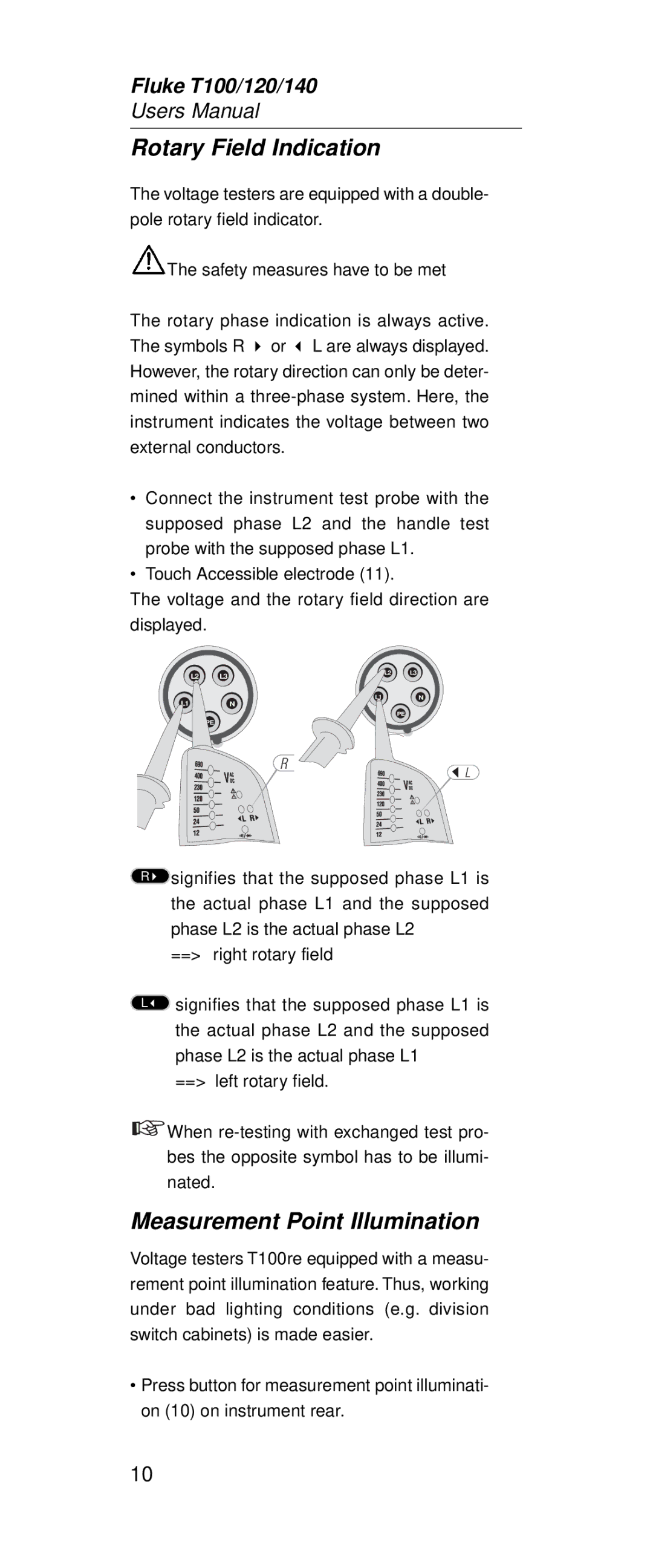
•Connect the instrument test probe with the supposed phase L2 and the handle test probe with the supposed phase L1.
•Touch Accessible electrode (11).
The voltage and the rotary field direction are displayed.
L2 | L3 | L2 | L3 |
L1N
L1N
PE
PE
R
L
Rsignifies that the supposed phase L1 is the actual phase L1 and the supposed phase L2 is the actual phase L2
==> right rotary field
Lsignifies that the supposed phase L1 is the actual phase L2 and the supposed phase L2 is the actual phase L1
==> left rotary field.
![]() When
When
Measurement Point Illumination
Voltage testers T100re equipped with a measu- rement point illumination feature. Thus, working under bad lighting conditions (e.g. division switch cabinets) is made easier.
•Press button for measurement point illuminati- on (10) on instrument rear.
10