Chapter 5 Directions for Bundled Software
Toolbar
Use the toolbar to navigate to other pages.
Alert Lamp
When the system is in healthy status, the alert lamp color is green. When the system is in abnormal status, the alert lamp color is red.
Switch Button
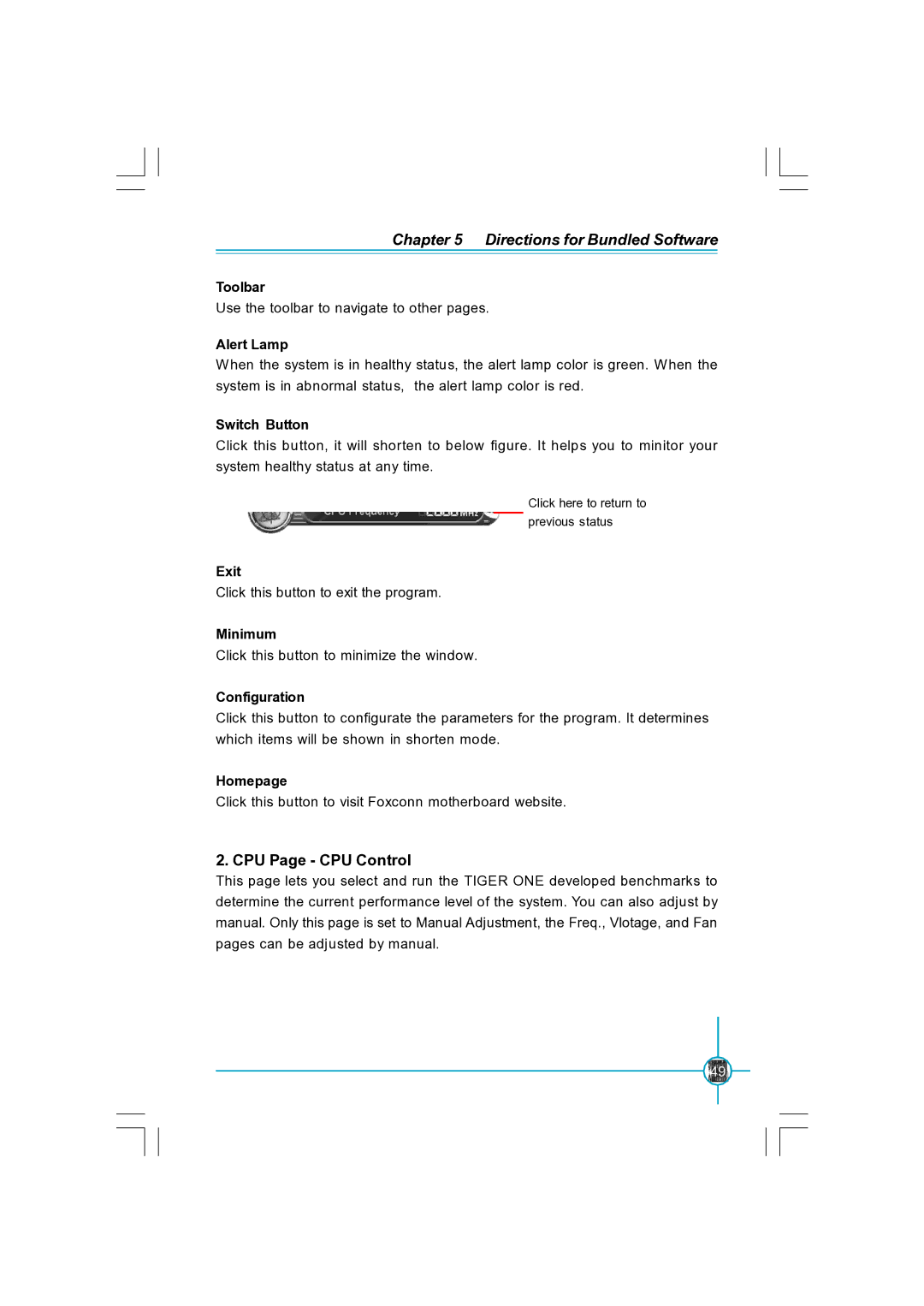
Click this button, it will shorten to below figure. It helps you to minitor your system healthy status at any time.
Click here to return to previous status
Exit
Click this button to exit the program.
Minimum
Click this button to minimize the window.
Configuration
Click this button to configurate the parameters for the program. It determines which items will be shown in shorten mode.
Homepage
Click this button to visit Foxconn motherboard website.
2. CPU Page - CPU Control
This page lets you select and run the TIGER ONE developed benchmarks to determine the current performance level of the system. You can also adjust by manual. Only this page is set to Manual Adjustment, the Freq., Vlotage, and Fan pages can be adjusted by manual.
49