Chapter 4 Driver CD Introduction
Installing Divers
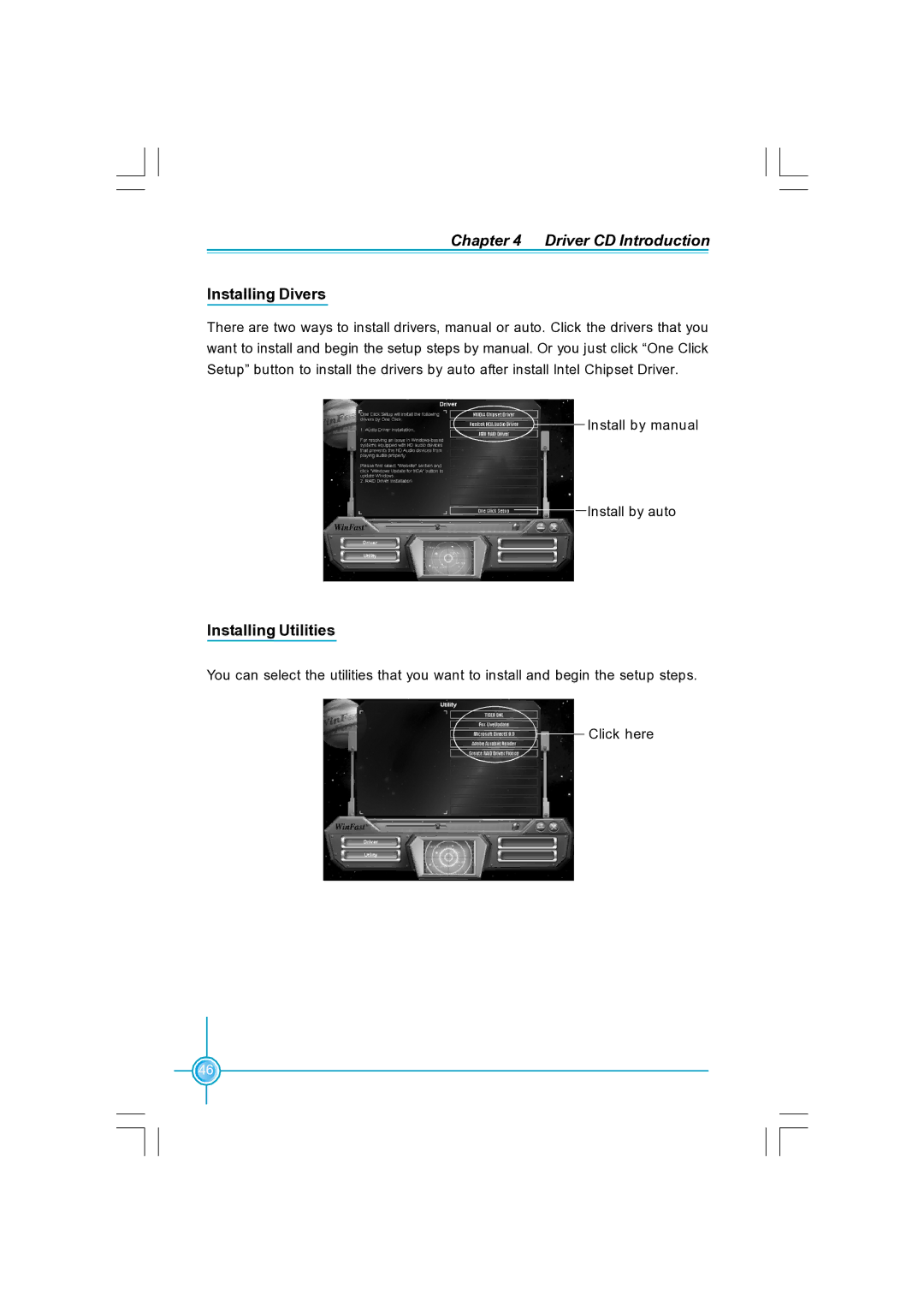
There are two ways to install drivers, manual or auto. Click the drivers that you want to install and begin the setup steps by manual. Or you just click “One Click Setup” button to install the drivers by auto after install Intel Chipset Driver.
![]()
![]() Install by manual
Install by manual
Install by auto
Installing Utilities
You can select the utilities that you want to install and begin the setup steps.
Click here
46