INSTALLATION INSTRUCTIONS
INSTALLATION INSTRUCTIONS
FOR “WSD”” SLEEVE
MOUNTING HARDWARE PROVIDED
ITEM | DESCRIPTION | QTY. | |
NO. | |||
|
| ||
1 | SCREW, #12A X 2” | 5 | |
|
|
|
WALL PREPARATION:
STEP 1 The wall opening required for a “WSD” SLEEVE is 17 1/4” high by 27 1/4” wide.
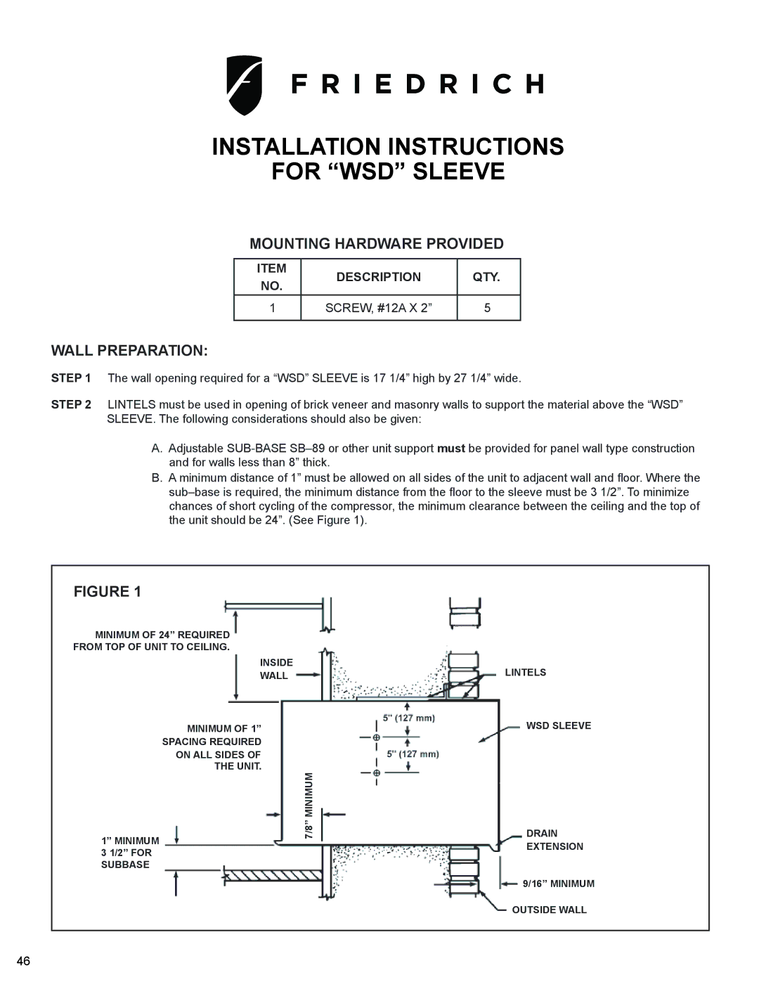
STEP 2 LINTELS must be used in opening of brick veneer and masonry walls to support the material above the “WSD” SLEEVE. The following considerations should also be given:
A.Adjustable
B.A minimum distance of 1” must be allowed on all sides of the unit to adjacent wall and floor. Where the
FIGURE 1
MINIMUM OF 24” REQUIRED FROM TOP OF UNIT TO CEILING.
INSIDE
WALL
MINIMUM OF 1”
SPACING REQUIRED
ON ALL SIDES OF
THE UNIT.
1” MINIMUM 3 1/2” FOR SUBBASE
7/8” MINIMUM
LINTELS
WSD SLEEVE
DRAIN
EXTENSION
9/16” MINIMUM
OUTSIDE WALL
46