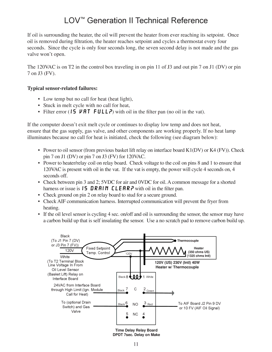
M3000 specifications
The Frymaster M3000 is a state-of-the-art frying solution that has gained popularity in commercial kitchens due to its impressive capabilities and advanced technologies. This fryer is designed to provide consistent, high-quality results while maintaining efficiency, making it an ideal choice for restaurants, fast food outlets, and foodservice operations.One of the significant features of the Frymaster M3000 is its oil management system. This advanced technology helps to extend the life of the cooking oil, reducing overall costs and improving food quality. The system monitors the oil's condition and alerts users when it is time to filter or change the oil, ensuring that the frying process remains uncompromised and that food is cooked to perfection.
The M3000 is equipped with a precise temperature control feature that allows users to set and maintain accurate cooking temperatures. This is critical in achieving optimal frying results, as various food items require different temperature settings for the best flavor and texture. The fryer also boasts rapid recovery times, meaning that it can quickly return to the desired temperature even after adding food, which is essential during busy peak times.
Additionally, the Frymaster M3000 incorporates a unique fry pot design that promotes even heat distribution throughout the cooking oil. This feature helps in reducing hot and cold spots, allowing for a more consistent frying experience. The design also facilitates easy cleaning, as the fry pot can be easily removed and maintained, thus improving overall kitchen hygiene.
Another notable characteristic of the M3000 is its user-friendly digital control interface. This intuitive system allows operators to program cooking times and temperatures easily, streamlining the frying process. With built-in diagnostic features, the fryer can notify users of potential issues, aiding in preventive maintenance and reducing downtime.
The Frymaster M3000 is also designed with safety in mind. Features such as auto shut-off, temperature limiters, and secure oil containment systems reduce the risk of accidents in busy kitchen environments. This attention to safety reassures operators that they are using a reliable piece of machinery.
In summary, the Frymaster M3000 is an exceptional commercial fryer that combines advanced technology, user-friendly controls, and a focus on safety and efficiency. Its oil management system, precision temperature control, rapid recovery, and ease of maintenance make it a preferred choice for foodservice professionals seeking reliable and high-quality frying solutions. With the M3000, consistent performance and culinary excellence are always within reach.

