M200, M400A, GranPower7000 (GP 7000F), M400R, M600 specifications
Fujitsu's M200R, M600R, M600, M400R, and GranPower 7000 (GP 7000F) models represent a suite of advanced computing solutions designed for various enterprise applications and high-performance tasks.Starting with the M200R, this model is known for its robust performance in data-intensive environments. It is equipped with advanced multi-core processors that enhance processing speed and efficiency. The M200R also supports virtualization technologies, allowing businesses to maximize resource utilization by running multiple operating systems simultaneously.
The M600R further extends these capabilities with an emphasis on reliability and scalability. It features redundant power supplies and cooling systems, ensuring uninterrupted operation during critical tasks. The M600R is ideal for medium to large enterprises requiring a dependable infrastructure that can grow with their operations. Its high memory capacity supports large-scale applications and extensive data analysis tasks.
Complementing this is the M600 model, which focuses on a balance between performance and energy efficiency. It integrates innovative power management technologies that help reduce overall operational costs while maintaining high processing capabilities. The M600's modular design allows for easy upgrades and maintenance, making it a flexible choice for evolving business needs.
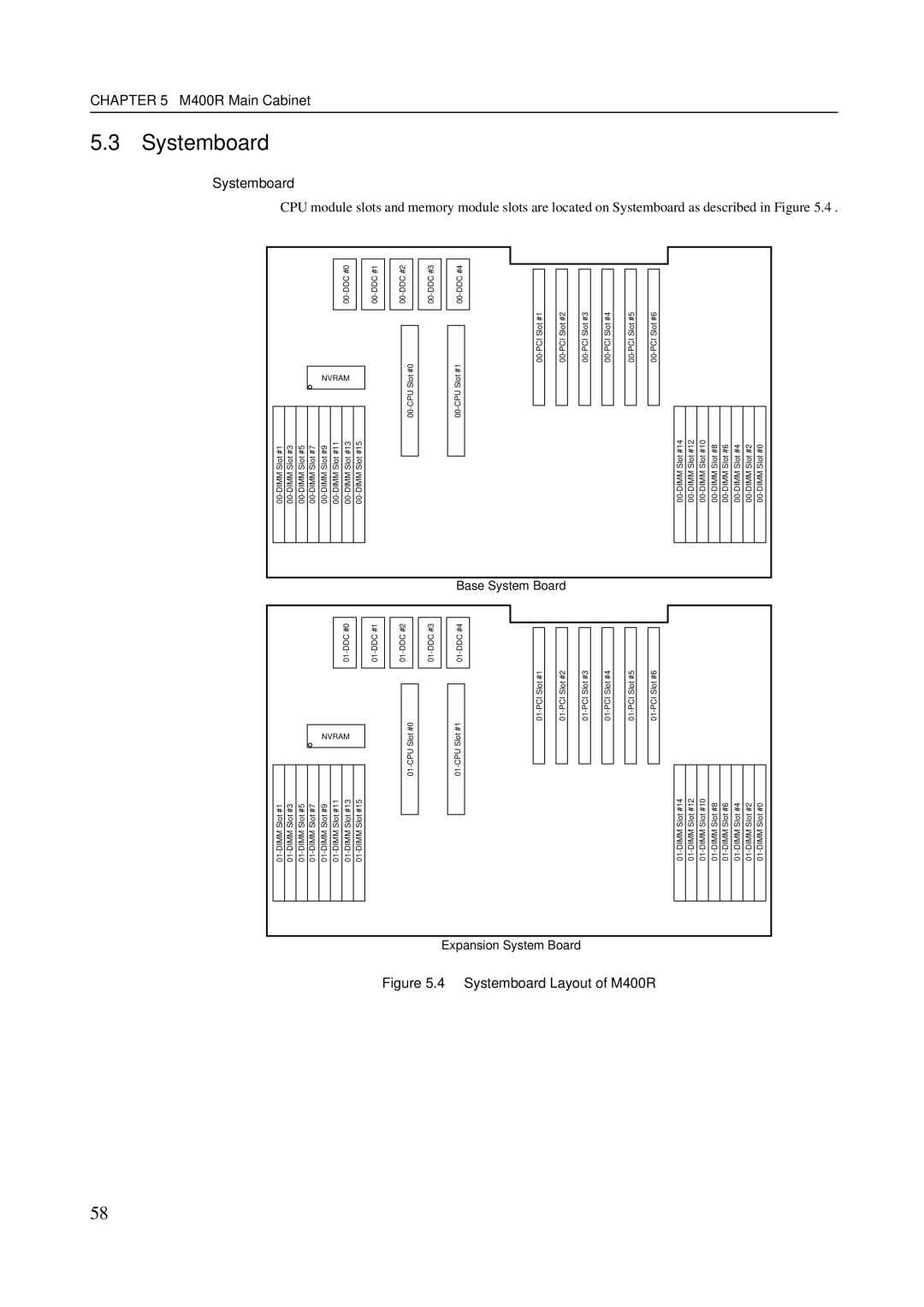
The M400R is specifically tailored for smaller organizations or those with less demanding workloads. Despite its compact size, it still features powerful processing capabilities and user-friendly management tools. The M400R’s cost-effectiveness and ease of deployment make it an attractive option for businesses looking to optimize their IT investments without compromising performance.
Finally, the GranPower 7000 (GP 7000F) stands out with its exceptional energy efficiency, providing an environmentally friendly solution for data centers. This model is notable for its advanced cooling technologies, which ensure optimal performance while minimizing energy consumption. The GP 7000F is particularly well-suited for high-density computing environments, offering enhanced security features and scalable architecture to accommodate future growth.
In summary, Fujitsu's M200R, M600R, M600, M400R, and GranPower 7000 are designed to meet diverse computing needs across different industries. Their main features include high-performance processors, scalability, energy efficiency, and advanced cooling technologies. By leveraging these sophisticated computing solutions, organizations can enhance their operational efficiency and better prepare for future challenges in an increasingly digital world.

