Chapter 5 Usage
■Setting the Clock Selector Jumper Plugs
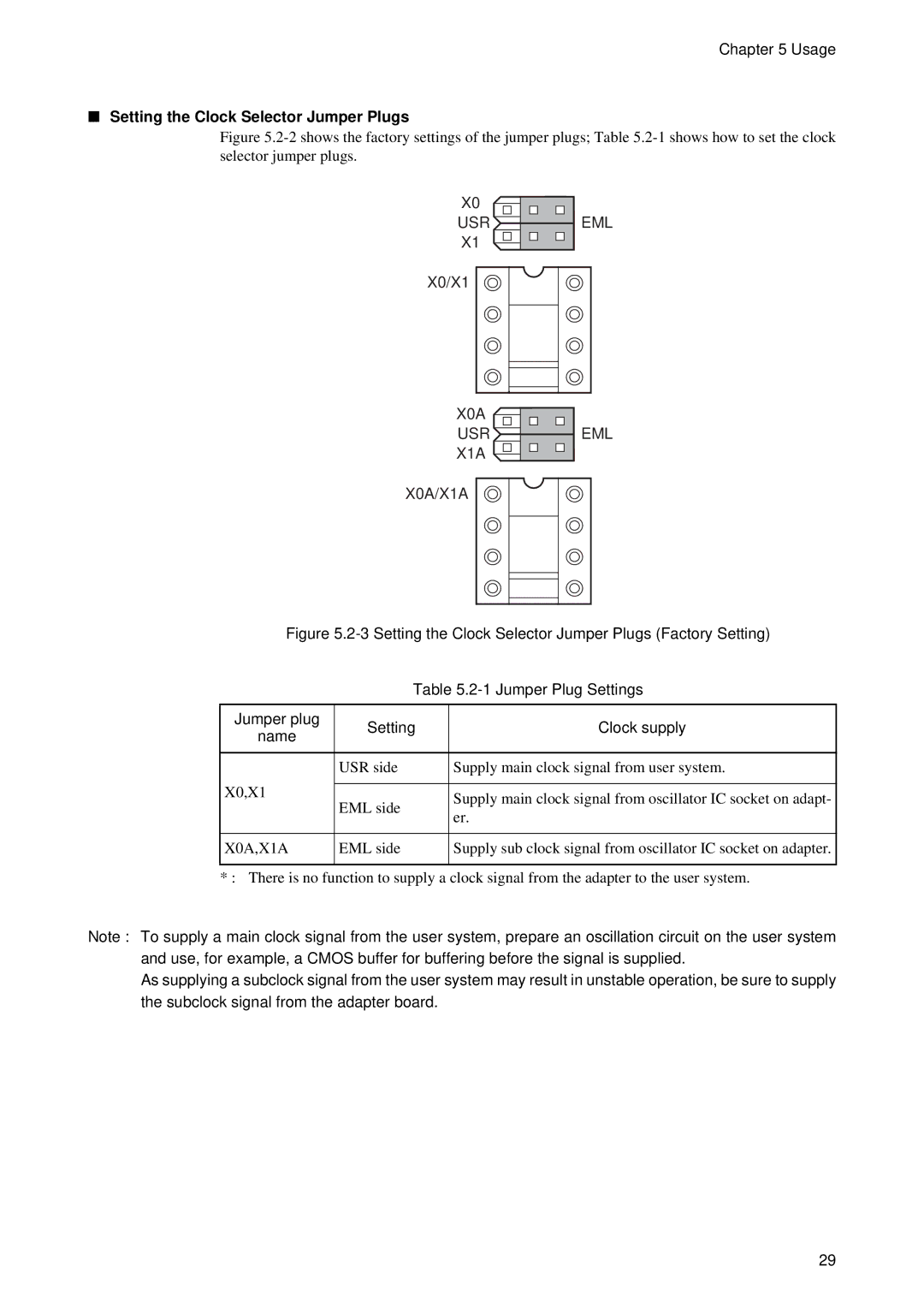
Figure 5.2-2 shows the factory settings of the jumper plugs; Table 5.2-1 shows how to set the clock selector jumper plugs.
X0 |
|
USR | EML |
X1 |
|
X0/X1
X0A |
|
USR | EML |
X1A |
|
X0A/X1A
Figure 5.2-3 Setting the Clock Selector Jumper Plugs (Factory Setting)
Table 5.2-1 Jumper Plug Settings
Jumper plug | Setting | Clock supply | |
name | |||
|
| ||
|
|
| |
| USR side | Supply main clock signal from user system. | |
X0,X1 |
|
| |
EML side | Supply main clock signal from oscillator IC socket on adapt- | ||
| |||
| er. | ||
|
| ||
|
|
| |
X0A,X1A | EML side | Supply sub clock signal from oscillator IC socket on adapter. | |
|
|
|
* : There is no function to supply a clock signal from the adapter to the user system.
Note : To supply a main clock signal from the user system, prepare an oscillation circuit on the user system and use, for example, a CMOS buffer for buffering before the signal is supplied.
As supplying a subclock signal from the user system may result in unstable operation, be sure to supply the subclock signal from the adapter board.
29