Chapter 3 Functions
3.2 Connector and IC Socket Specifications
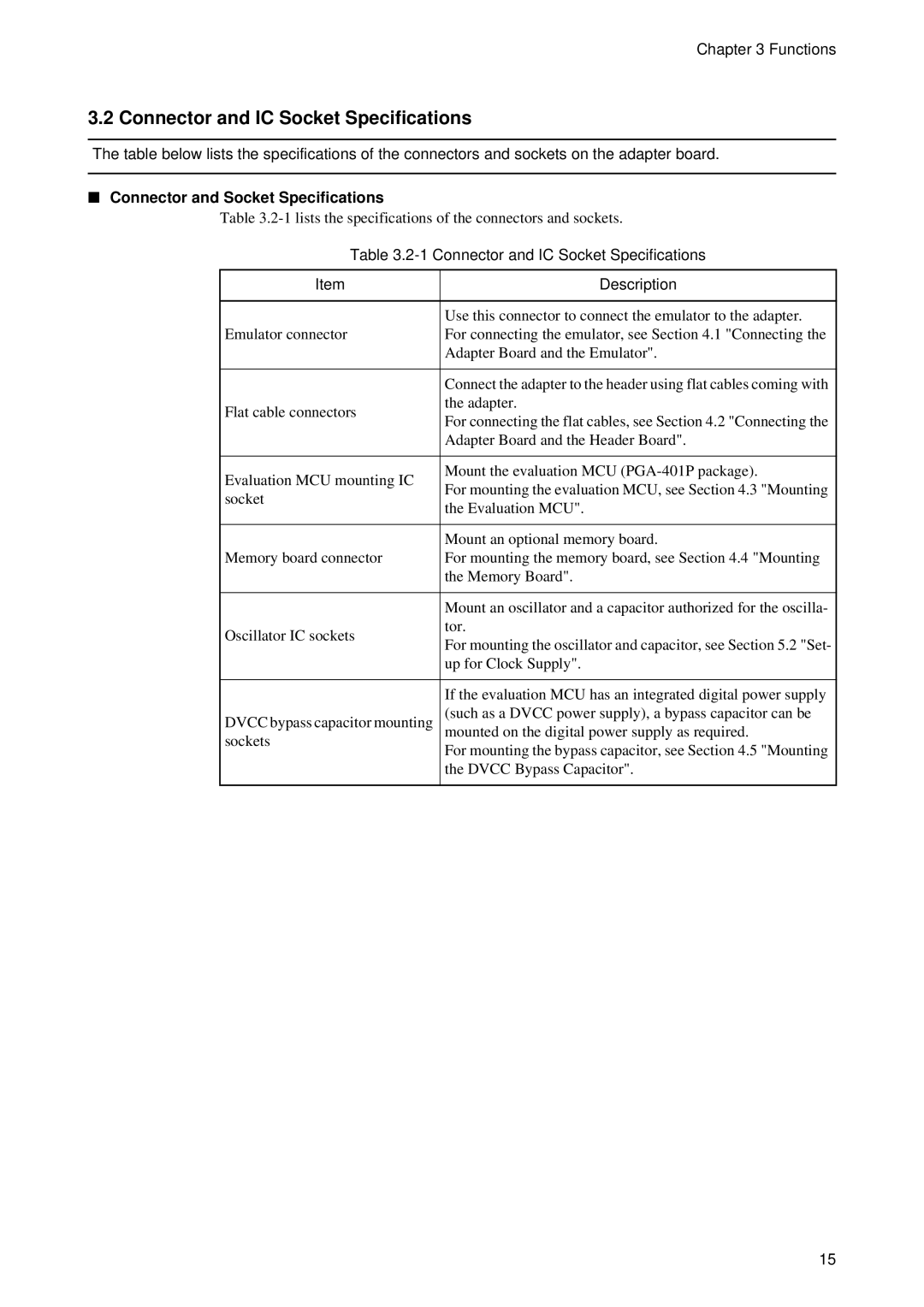
The table below lists the specifications of the connectors and sockets on the adapter board.
■Connector and Socket Specifications
Table
Table | ||
|
| |
Item | Description | |
|
| |
| Use this connector to connect the emulator to the adapter. | |
Emulator connector | For connecting the emulator, see Section 4.1 "Connecting the | |
| Adapter Board and the Emulator". | |
|
| |
| Connect the adapter to the header using flat cables coming with | |
Flat cable connectors | the adapter. | |
For connecting the flat cables, see Section 4.2 "Connecting the | ||
| ||
| Adapter Board and the Header Board". | |
|
| |
Evaluation MCU mounting IC | Mount the evaluation MCU | |
For mounting the evaluation MCU, see Section 4.3 "Mounting | ||
socket | ||
the Evaluation MCU". | ||
| ||
|
| |
| Mount an optional memory board. | |
Memory board connector | For mounting the memory board, see Section 4.4 "Mounting | |
| the Memory Board". | |
|
| |
| Mount an oscillator and a capacitor authorized for the oscilla- | |
Oscillator IC sockets | tor. | |
For mounting the oscillator and capacitor, see Section 5.2 "Set- | ||
| ||
| up for Clock Supply". | |
|
| |
| If the evaluation MCU has an integrated digital power supply | |
DVCC bypass capacitor mounting | (such as a DVCC power supply), a bypass capacitor can be | |
mounted on the digital power supply as required. | ||
sockets | For mounting the bypass capacitor, see Section 4.5 "Mounting | |
| ||
| the DVCC Bypass Capacitor". | |
|
| |
15
