Chapter 5 Usage
5.2 Setting the Clock Supply Circuit
To supply a clock signal from the adapter board to the main clock (X0/X1) and subclock (X0A/X1A) of the eval- uation MCU, install an oscillator and a capacitor on the oscillator IC sockets (SC2 and SC3) on the adapter board, respectively. Figure
■Installing the Oscillator
To supply a clock signal from the adapter board to the main clock (X0/X1) and subclock (X0A/X1A) of the evaluation MCU, install an oscillator and a capacitor on the oscillator IC sockets (SC2 and SC3) on the adapter board, respectively. Figure
Adapter Board |
|
| User system | |
|
| (Board) | ||
|
|
|
| |
X1 | USR |
|
| X1 |
X1 |
|
|
| |
| EML |
|
|
|
X0 | USR |
|
| X0 |
X0 |
|
|
| |
| EML | X0/X1 |
|
|
|
|
| Flat cable | |
Evaluation | 1 | 8 |
| |
2 | 7 |
| connector | |
|
|
| ||
MCU | 3 | 6 |
| (MCU mounting |
4 | 5 |
| ||
| GND |
| GND | part) |
|
|
| ||
| USR |
|
| X1A/PF6 |
X1A | X1 |
|
|
|
| EML |
|
|
|
| USR |
|
| X0A/PF5 |
X0A | X0 |
|
|
|
| EML | X0A/X1A |
|
|
| 1 |
|
| |
| 8 |
|
| |
| 2 | 7 |
|
|
| 3 | 6 |
|
|
| 4 | 5 |
|
|
| GND |
| GND |
|
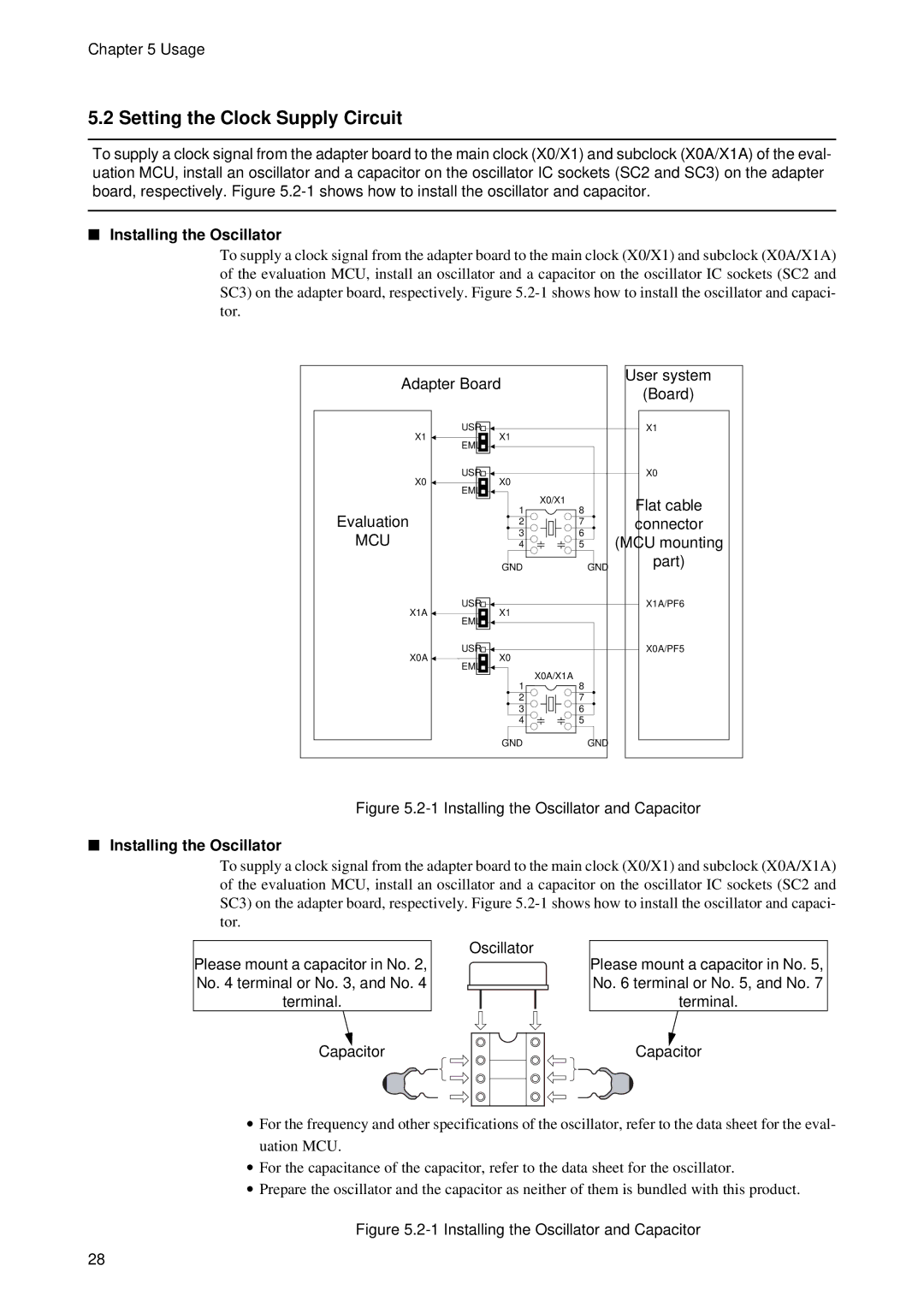
Figure 5.2-1 Installing the Oscillator and Capacitor
■Installing the Oscillator
To supply a clock signal from the adapter board to the main clock (X0/X1) and subclock (X0A/X1A) of the evaluation MCU, install an oscillator and a capacitor on the oscillator IC sockets (SC2 and SC3) on the adapter board, respectively. Figure
Please mount a capacitor in No. 2, No. 4 terminal or No. 3, and No. 4 terminal.
Oscillator
Please mount a capacitor in No. 5, No. 6 terminal or No. 5, and No. 7 terminal.
Capacitor
Capacitor
•For the frequency and other specifications of the oscillator, refer to the data sheet for the eval- uation MCU.
•For the capacitance of the capacitor, refer to the data sheet for the oscillator.
•Prepare the oscillator and the capacitor as neither of them is bundled with this product.
Figure 5.2-1 Installing the Oscillator and Capacitor
28