Chapter 3 Functions
3.1 Function Specifications
Table
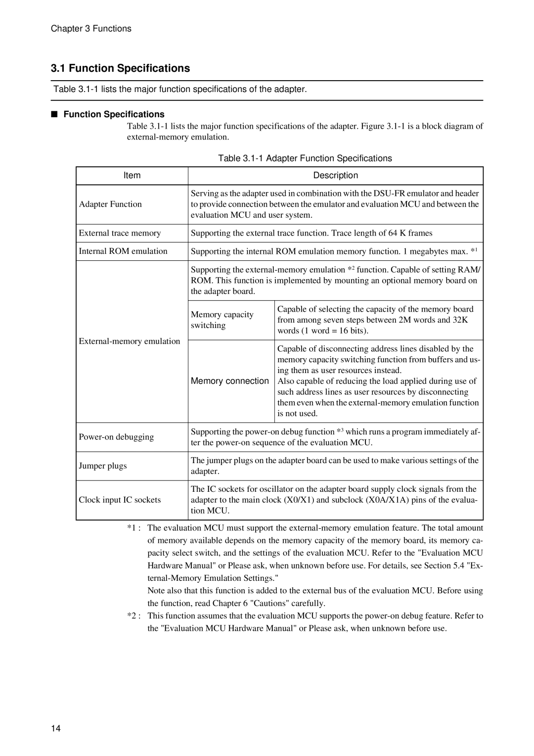
■Function Specifications
Table
| Table | ||
|
|
| |
Item |
| Description | |
|
| ||
| Serving as the adapter used in combination with the | ||
Adapter Function | to provide connection between the emulator and evaluation MCU and between the | ||
| evaluation MCU and user system. | ||
|
| ||
External trace memory | Supporting the external trace function. Trace length of 64 K frames | ||
|
| ||
Internal ROM emulation | Supporting the internal ROM emulation memory function. 1 megabytes max. *1 | ||
|
| ||
| Supporting the | ||
| ROM. This function is implemented by mounting an optional memory board on | ||
| the adapter board. |
| |
|
|
| |
| Memory capacity | Capable of selecting the capacity of the memory board | |
| from among seven steps between 2M words and 32K | ||
| switching | ||
| words (1 word = 16 bits). | ||
|
| ||
|
| ||
| Capable of disconnecting address lines disabled by the | ||
|
| ||
|
| memory capacity switching function from buffers and us- | |
|
| ing them as user resources instead. | |
| Memory connection | Also capable of reducing the load applied during use of | |
|
| such address lines as user resources by disconnecting | |
|
| them even when the | |
|
| is not used. | |
|
|
| |
Supporting the | |||
ter the | |||
| |||
|
| ||
Jumper plugs | The jumper plugs on the adapter board can be used to make various settings of the | ||
adapter. |
| ||
|
| ||
|
| ||
| The IC sockets for oscillator on the adapter board supply clock signals from the | ||
Clock input IC sockets | adapter to the main clock (X0/X1) and subclock (X0A/X1A) pins of the evalua- | ||
| tion MCU. |
| |
|
|
| |
*1 : The evaluation MCU must support the
Note also that this function is added to the external bus of the evaluation MCU. Before using the function, read Chapter 6 "Cautions" carefully.
*2 : This function assumes that the evaluation MCU supports the
14