Chapter 2 Product Description
2.1 System Configuration
Used in combination with the header, the adapter is connected to the emulator and the user system.
■System Configuration
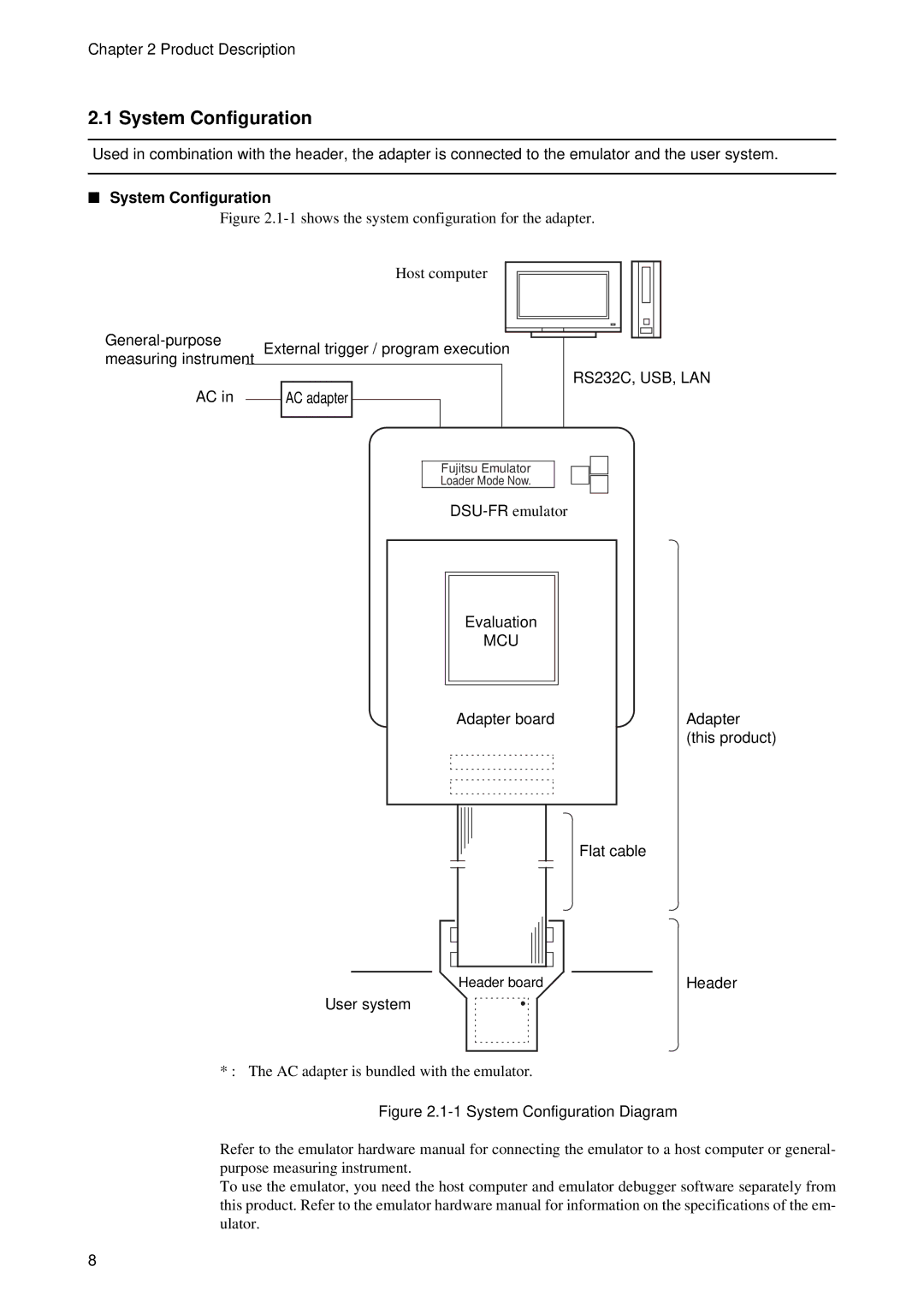
Figure 2.1-1 shows the system configuration for the adapter.
Host computer
measuring instrument External trigger / program execution
RS232C, USB, LAN
AC in |
| AC adapter |
|
Fujitsu Emulator
Loader Mode Now.
Evaluation
MCU
Adapter board
Adapter (this product)
Flat cable
Header board | Header |
User system
* : The AC adapter is bundled with the emulator.
Figure 2.1-1 System Configuration Diagram
Refer to the emulator hardware manual for connecting the emulator to a host computer or general- purpose measuring instrument.
To use the emulator, you need the host computer and emulator debugger software separately from this product. Refer to the emulator hardware manual for information on the specifications of the em- ulator.
8