Disk Drive Product Manual
MHV2120AT, MHV2100AT, MHV2080AT MHV2060AT, MHV2040AT
Handling of This Manual
For Safe Operation
Revision History
This page is intentionally left blank
Overview of Manual
Preface
Operating Environment
Conventions for Alert Messages
Conventions
Liability Exception
This page is intentionally left blank
Important Alert Messages
Important Alert Items
Damage Interface cable connection
This page is intentionally left blank
Manual Organization
Disk Drive Maintenance Manual
Disk Drive Product Manual
This page is intentionally left blank
Contents
Theory of Device Operation
Installation Conditions
Interface
Contents
101
Write Multiple EXT X’39’ Option customizing
Operations
Glossary GL-1 Acronyms and Abbreviations AB-1 Index IN-1
Figures
Illustrations
Execution example of Read Multiple command
Tables
Surface temperature measurement points and standard
25 Relationship between combination of Identifier
This page is intentionally left blank
Device Overview
Functions and performance
Features
Adaptability
High resistance against shock
Error correction and retry by ECC
Connection to ATA interface
Data buffer
Specifications summary
Device Specifications
Specifications 1
Model and product number
Specifications 2
Examples of model names and product numbers
Input Voltage
Power Requirements
Ripple
Current and power dissipation
Current Requirements and Power Dissipation
Current fluctuation Typ. at +5 V when power is turned on
Environmental Specifications
Power on/off sequence
Environmental specifications
Shock and vibration specification
Acoustic noise specification
Acoustic Noise
Shock and Vibration
Data assurance in the event of power failure
Service life
Reliability
Mean time between failures Mtbf
Unrecoverable read error
Error Rate
Positioning error
Media Defects
Advanced Power Management
Advanced Power Management
Advanced Power Management
This page is intentionally left blank
Device Configuration
Device Configuration
ATA interface
System Configuration
2 1 drive connection
Read/write circuit
3 2 drives connection
2 drives configuration
Installation Conditions
Dimensions
Dimensions
Integration Guidance C141-E144
Mounting
Orientation
Limitation of mounting
Frame
PCA
Location of breather
Ambient temperature
Handling cautions
Service area
Handling cautions
Cable Connections
Device connector
Cable connector specifications
Cable connector specifications
Device connection
FCI
Power supply connector CN1
Jumper Settings
Location of setting jumpers
Master drive-slave drive setting
Factory default setting
14 Csel setting
Csel setting
16 Example 2 of cable select
Power up in standby setting
Theory of Device Operation
Subassemblies
Outline
Disk
Spindle
Air filter
Circuit Configuration
Servo circuit
Spindle motor driver circuit
Power supply configuration
PCA
Power-on operation sequence
Power-on Sequence
Self-calibration
Self-calibration contents
Execution timing of self-calibration
Command processing during self-calibration
Read/write preamplifier PreAMP
Read/write Circuit
Write circuit
Write precompensation
AGC circuit
Read circuit
Programmable filter circuit
FIR circuit
Digital PLL circuit
D converter circuit
Viterbi detection circuit
Servo control circuit
Servo Control
Microprocessor unit MPU
Power amplifier
Servo burst capture circuit
A converter DAC
VCM current sense resistor CSR
Driver circuit
Inner guard band
Data-surface servo format
Data area
Outer guard band
Physical sector servo configuration on disk surface
Servo frame format
Operation to move the head to the reference cylinder
Actuator motor control
Seek operation
Track following operation
Acceleration mode
Start mode
Stable rotation mode
Spindle motor control
This page is intentionally left blank
Interface
Physical Interface
Interface signals
Signal assignment on the interface connector
Signal assignment on the connector
DA1 PDIAG-, Cblid DA0 DA2
Dasp GND
Diow
Mstr
Stop
Dior
Cblid
Pdiag
Dasp
Iordy
Logical Interface
I/O registers
1 I/O registers
DA2 DA1 DA0
Error register X’1F1’
Command block registers
Data register X’1F0’
UNC Idnf
SET Multiple Mode
Features register X’1F1’
Sector Count register X’1F2’
Cylinder Low register X’1F4’
Sector Number register X’1F3’
Cylinder High register X’1F5’
DEV HS3 HS2 HS1 HS0
Device/Head register X’1F6’
Status register X’1F7’
BSY
Interface
Control block registers
Command register X’1F7’
Alternate Status register X’3F6’
Command code and parameters
Host Commands
Device Control register X’3F6’
HOB Srst
Parameter Used
Command code and parameters 1
EXT Write Multiple FUA EXT Flush Cache EXT
Command code and parameters 2
Host Commands
Command descriptions
Host Commands
Recalibrate X’10’ to X’1F’
MSB
Read Sectors X’20’ or X’21’
End head No. / LBA MSB
Write Sectors X’30’ or X’31’
1F7HST Status information 1F6HDH
Write Verify X’3C’
Read Verify Sectors X’40’ or X’41’
Seek X’70’ to X’7F’
Diagnostic code
Execute Device Diagnostic X’90’
Host Commands
Initialize Device Parameters X’91’
Download Microcode X’92’
Operation of Download Microcode
Standby Immediate X’94’ or X’E0’
Unload Feature Unload Immediate Command
Host Commands
Standby X’96’ or X’E2’
Idle X’97’ or X’E3’
Interface
’FF’
Check Power Mode X’98’ or X’E5’
Sleep X’99’ or X’E6’
Smart X’B0
Features register values subcommands and functions 1
Smart Enable Operations
Features register values subcommands and functions 2
Smart Disable Operations
Smart Read LOG
’DB’ Smart ENABLE/DISABLE Auto OFF-LINE
Features register values subcommands and functions 3
Smart Return Status
Host Commands
1FF
Format of device attribute value data
Format of insurance failure threshold value data
Attribute ID
Data format version number
Current attribute value
Status Flag
Attribute value for the worst case so far
Raw attribute value
Self-test execution status
10 Off-line data collection status
11 Self-test execution status
12 Off-line data collection capability
Off-line data collection capability
Failure prediction capability flag
13 Failure prediction capability flag
14 Error logging capability
Error logging capability
Check sum
Insurance failure threshold
Smart error logging
16 Data format of Smart Summary Error Log
Error data structure
Command data structure
Total number of drive errors
17 Data format of Smart Comprehensive Error Log
18 Smart self-test log data format
Smart self-test
1FC
Self-test number
Test span
19 Selective self-test log data structure
Current LBA under test
Current span under test
20 Selective self-test feature flags
Feature flags
Selective self-test pending time min
Device Configuration Restore
Device Configuration XB1
Device Configuration Freeze
Device Configuration Identify
Device Configuration Freeze Lock FR = C1h
Device Configuration Restore FR = C0h
Device Configuration Identify FR = C2h
Device Configuration SET FR = C3h
Interface
21 Device Configuration Identify data structure
Interface
Read Multiple X’C4’
Execution example of Read Multiple command
MSB
Write Multiple X’C5’
Interface
SET Multiple Mode X’C6’
Interface
Read DMA X’C8’ or X’C9’
End head No. / LBA MSB
Write DMA X’CA’ or X’CB’
Interface
Read Buffer X’E4’
Flush Cache X’E7’
Write Buffer X’E8’
Identify Device X’EC’
Identify Device DMA X’EE’
’3FFF’
22 Information to be read by Identify Device command 1
22 Information to be read by Identify Device command 2
Word
Command without interrupt supports 2, 4, 8 and 16 sectors
= Supports the Host Protected Area feature set
= Supports the CFA Compact Flash Association feature set
Interface
Host Commands
Interface
Host Commands
Word Bit Reserved Security level High, 1 Maximum
23 Features register values and settable modes
SET Features X’EF’
’BB’
’CC’
Data Transfer Mode
Advanced Power Management APM
Automatic Acoustic Management AAM
24 Contents of Security SET Password data
At command issuance I-O register contents 1F7hCM
When the user password is selected
When the master password is selected
Security UNLOCKX’F2’
Interface
Security Erase Prepare X’F3’
Security Erase Unit X’F4’
Security Freeze Lock X’F5’
At command issuance I-O register contents 1F7hCM
26 Contents of security password
Interface
Read Native MAX Address X’F8’
SET MAX Address
SET MAX X’F9’
SET MAX SET Password FR = 01h
SET MAX Lock FR = 02h
SET MAX Unlock FR = 03h
SET MAX Freeze Lock FR = 04h
Host Commands
Read Sectors EXT X’24’ Option customizing Description
Read DMA EXT X’25’ Option customizing Description
Error reporting conditions
Read Multiple EXT X’29’ Option customizing Description
Read LOG EXT X2F Optional command Customize Description
Host Commands
Write Sectors EXT X’34’ Option customizing Description
Write DMA EXT X’35’ Option customizing Description
SET MAX Address EXT X’37’ Option customizing Description
SET MAX LBA
Write Multiple EXT X’39’ Option customizing Description
Write DMA FUA EXT X’3D’ Option customizing Description
Write LOG EXT X’3F’ Optional command Customize Description
Host Commands
Read Verify Sectors EXT X’42 Option customizing Description
Write Multiple FUA EXT X’CE’ Option customizing Description
Flush Cache EXT X’EA’ Option customizing Description
27 Command code and parameters 1
Error posting
27 Command code and parameters 2
PIO Data transferring commands from device to host
Command Protocol
Execute Device Diagnostic Initialize Device Parameters
Read Sectors Command protocol
Protocol for command abort
PIO Data transferring commands from host to device
Write Sectors command protocol
Commands without data transfer
DMA data transfer commands
Other commands
Read Multiple EXT Write Multiple EXT/FUA EXT Sleep
Read DMA EXT Write DMA EXT/FUA EXT Indentify Device DMA
Normal DMA data transfer
Overview
Ultra DMA Feature Set
Ultra DMA data in commands
Phases of operation
Initiating an Ultra DMA data in burst
Data in transfer
Pausing an Ultra DMA data in burst
Terminating an Ultra DMA data in burst
Ultra DMA Feature Set
Interface
Initiating an Ultra DMA data out burst
Ultra DMA data out commands
Data out transfer
Pausing an Ultra DMA data out burst
Terminating an Ultra DMA data out burst
Interface
Ultra DMA CRC rules
28 Recommended series termination for Ultra DMA
Series termination required for Ultra DMA
DIOR-HDMARDY-HSTROBE
DIOW-STOP
PIO data transfer
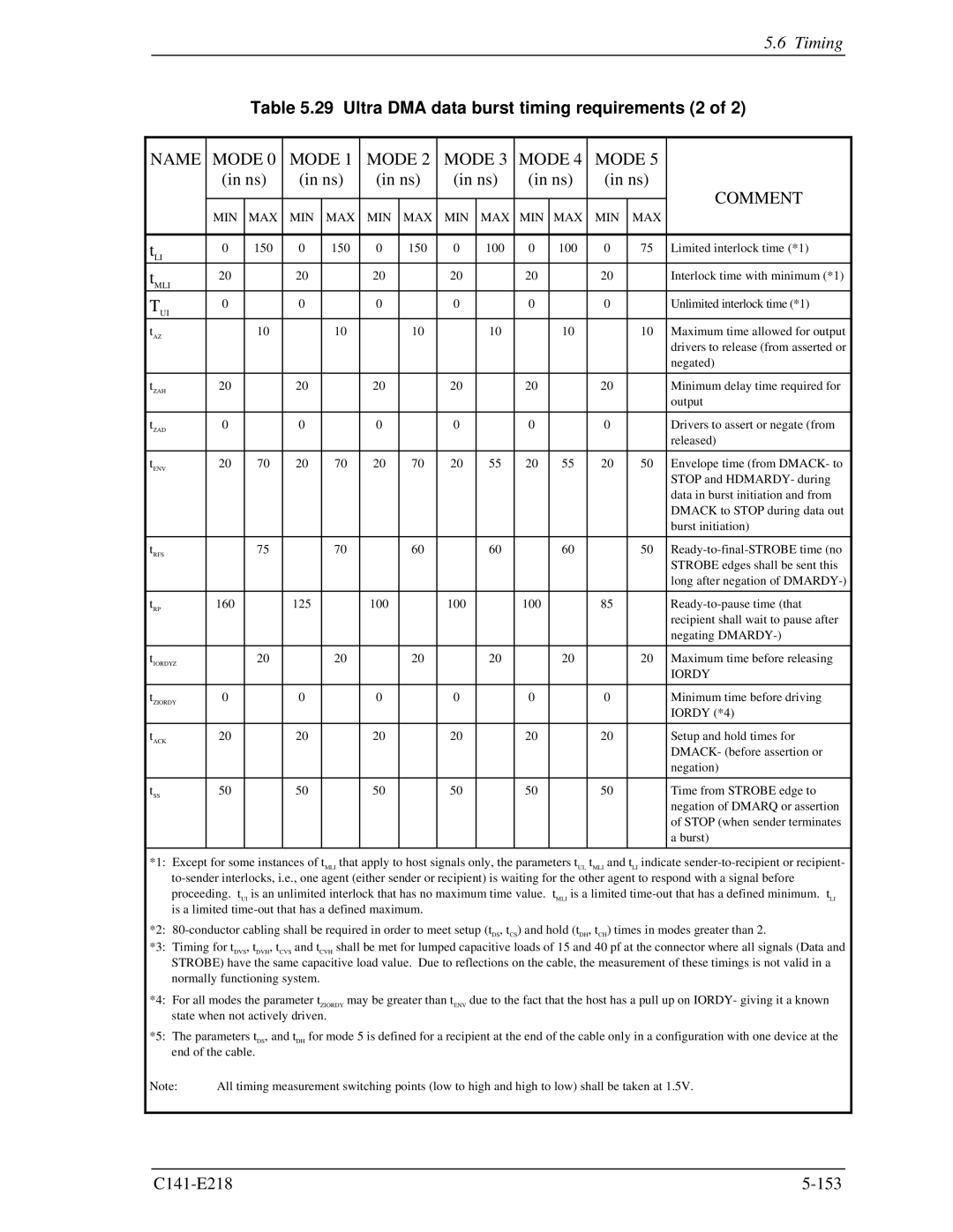
Timing
PIO data transfer timing
Multiword data transfer
10 Multiword DMA data transfer timing mode
11 Initiating an Ultra DMA data in burst
Ultra DMA data transfer
Strobe
Name Mode Comment
MIN MAX
29 Ultra DMA data burst timing requirements 2
30 Ultra DMA sender and recipient timing requirements
Mode Name Comment
Dstrobe at device
Sustained Ultra DMA data in burst
DD150 at device Dstrobe at host
DD150 at host
Dmarq
Host pausing an Ultra DMA data in burst
Dmack
Hdmardy
Stop
Device terminating an Ultra DMA data in burst
Host
Host terminating an Ultra DMA data in burst
DA0, DA1, DA2 CS0, CS1
16 Initiating an Ultra DMA data out burst
Hstrobe at host DD150 at host
Sustained Ultra DMA data out burst
Hstrobe at device DD150 at device
Device DMACK- host Stop host DDMARDY- device
Device pausing an Ultra DMA data out burst
Hstrobe host DD150 Host
19 Host terminating an Ultra DMA data out burst
Host terminating an Ultra DMA data out burst
Dmarq device DMACK- host
Device terminating an Ultra DMA data out burst
DD150 Host
Master and slave devices are present 2-drives configuration
Power-on and reset
Only master device is present
Operations
Response to power-on
Device Response to the Reset
Response to power-on
Response to hardware reset
Response to hardware reset
Response to software reset
Response to software reset
Response to diagnostic command
Response to diagnostic command
Power save mode
Power Save
Active mode
Active idle mode
Sleep mode
Standby mode
Defect Processing
Power commands
Spare area
Sector slip processing
Alternating processing for defective sectors
Track slip processing
Automatic alternating processing
Automatic alternating processing
Data buffer structure
Read-ahead Cache
8MB buffer 8,388,608 bytes
Caching operation
Commands that are targets of caching
Data that is a target of caching
Invalidating caching-target data
Smart
Miss-hit
Using the read segment buffer
Sequential hit
Full hit
Partial hit
Write Cache
Command that are targets of caching
Cache operation
Invalidation of cached data
Reset response
Status report in the event of an error
Caching function when power supply is turned on
Enabling and disabling
Write Cache
This page is intentionally left blank
Glossary
Rotational delay
Power save mode
PIO Programmed input-output
Positioning
VCM
Status
This page is intentionally left blank
Acronyms and Abbreviations
This page is intentionally left blank
AAM
Index
Index
Host terminating ultra DMA data
Read Native MAX Address
Read Sectors Command
Surface temperature measurement
This page is intentionally left blank
Japan
Comment Form
This page is intentionally left blank
C141-E218-01EN
MHV2120AT, MHV2100AT, MHV2080AT, MHV2060AT, MHV2040AT
This page is intentionally left blank