Video Plotter
00080933204
Safety Instructions
Table of Contents
SP-1
Iii
IN-1
Foreword
Features
Word to the Owner of the RP-250
Operational Overview
General
Video plotter controls
Controls
FR-2105 series radar display unit
AIS controls
Choosing Display Mode
Video plotter display
Item and default setting Default selected at above
Choosing Presentation Mode
About the radar/video plotter display
Chart, cursor position correction
Charts
Displaying a chart
Chart position correction
Hiding/Showing graphics
Setting up the Video Plotter Display
Canceling chart position correction
Cursor position correction
Hiding/Showing nav data
NAV Information 1 menu
NAV Information 2 menu
For manual input of position item 4, do the following
NAV Information 3 menu
Stopping Plotting of Other Ship’s Track
Track
Stopping Plotting of Own Ships Track
OWN SHIP, Target Plot menu
Finding track memory used
Track Plotting Interval
Choosing track plotting interval
Memory in USE display
Erasing Track
Smoothing
Plotter Erase menu
Other Ship Track Color
Own Ship Track Color
Target Plot Color menu
Entering Marks/Lines
MARKS, Lines
Choosing Method of Entry
Entering marks/lines at cursor or own ship position
Line change feature
Entering marks at desired position
Erasing individual marks
Mark/Line Color
Erasing Marks/Lines
Erasing all marks and all lines
Finding Mark/Line Memory Used
Entering waypoints at cursor position
WAYPOINTS, Navigation Lines
Entering Waypoints
Entering waypoints at specific position
Entering waypoints at own ship position
Waypoint List
WPT List
Displaying waypoints from a navigator
Displaying Waypoints
Displaying waypoints
Waypoint menu
Deleting individual waypoints
Deleting Waypoints
Navigation Lines
Deleting all waypoints
Nav line list
Adding waypoints to navigation lines
Removing waypoints from navigation lines
Deleting individual navigation lines
Setting up navigation lines
NAV Line menu
BWR
Displaying navigation lines
Formatting Memory Cards
RECORDING, Replaying Data
Record menu
Replaying Data
Recording Data
Replay Card 1 menu
Video PLOTTER, Initial Setting menu
Initial Settings
Other Plotter Functions
Longitude Error Table on 96 nm range scale
Distance error in direction of longitude due to latitude
2256 4444 6496 8350 9950 1248 2202 2786 2980
This page intentionally left blank
AIS Operation
Turning AIS Feature On/Off
AIS symbols
AIS1 menu
Activating Targets
Turning AIS Display On/Off
Activated target
Sleeping all AIS targets
Sleeping Targets
Sleeping an AIS target
Sleeping target
Basic target data
Displaying Target Data
Activating all sleeping AIS targets
Activated target selected for data display
Extended target data
Extended data display
Displaying messages manually
Lost Target
Messages
Lost target
Safety related message
Automatically displaying messages
Sample history displays
History Display
Turning history display on/off
AIS2 menu
AIS Symbol Color
Choosing history display attributes
Automatic Target Activation
Lost Target Range
ROT Display Setting
ROT display
Combining AIS with Arpa fusion
AIS3 menu
AIS system messages
AIS System Messages
Message Meaning
AIS Alarm Message
Replacing the Battery in the Memory Card
Maintenance
Replacing the Battery on the RP Board
Battery for Battery Type Code Number
System Error
Necessary parts
Installation of Video Plotter KIT
Tabletop/Console Type
Name Type Qty Code No Remarks
Control head
Display unit
Setting catch to hole in stay
Display unit, inside view
Stay fixed
Fastening the M-card assy. to the right arm cover
Display pedestal, front view
Display pedestal, top view
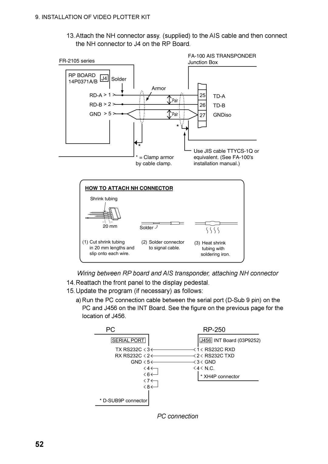
PC connection
TD-B
FR-2105 Test
Test results
AIS Data
Separate Type Control Head
Fasten with M4 x 8 screw Fasten with M3 x 8 screws 2 pcs
Installation of Video Plotter KIT
Input sentences RP Board, J4
Appendix
Digital Interface IEC
Data reception
Schematic diagram
Load requirements as listener
Interface Function
COG, SOG, HDG, ROT
Main Board Modification IEC 60936-1 related items
STW selected on menu
Conditions Which Display the Alarm for WT
SOG selected on menu
Menu Tree
Video plotter
Enter WPT, NAV Line OWN SHIP, Target Plot
AIS
Specifications of Video Plotter
RP-250
Index
IN-1