THD SATELLITE COMPASS
SC-110
00014854600
OME72570A20 OME72570A20
DAMI SC-110
A2 JUN
Safety Instructions for the Operator
Safety Instructions for the Installer
SAFETY INSTRUCTIONS
ELECTRICAL SHOCK HAZARD
TABLE OF CONTENTS
TABLE OF CONTENTS
SYSTEM CONFIGURATION
SPECIFICATIONS
3 MAINTENANCE, TROUBLESHOOTING
INTECONNECTION DIAGRAM
APPENDIX
AP-1
Features
FOREWORD
A Word to the Owner of the SC-110
SYSTEM CONFIGURATION
System configuration
EQUIPMENT LIST
Standard supply
Optional equipment
Name
SPECIFICATIONS OF THD SATELLITE COMPASS SC-110
POWER SUPPLY
SP
1 GENERAL
COATING COLOR
SP
1 INSTALLATION
Installing the antenna above superstructures
Installing the antenna below superstructures
1.1Mounting Considerations
80 +80
Mast diameter
Separation distance minimum
Separation degrees
1.1.2Display unit, processor unit
1.2Installing the Antenna Unit
Installation post
Fastening antenna unit to a post
1. INSTALLATION
Set the antenna unit to the flange Flat washer
Spring washer Nut Torque 29.58 Nm
Coating bolt, nut and washer with silicone rubber
Antenna element
Coat bolt threads with
1.3Installing the Processor Unit
1.3.1Bulkhead mount
Bulkhead mount
1.3.2Deck mount
Processor unit orientation, deck mounting
1.3.3Installation on the underside of a desk
Mounting on underside of desk
Processor Unit, rear view
1.4Installing the Display Unit
1.4.1Desktop, overhead mounting
1.4.2Flush mount
1-10
1-11
Flush mount “S”
Flush mount “S” kit
Type OP20-17,Code No
1.5Wiring
Wiring
1-12
How to install the optional antenna cable set
1-13
Sectional view of coaxial cable DPYC-1.5
How to attach connector N-P-8DFB
How to attach connector N-P-8DFB
1-14
1.6Initial Settings
1.6.1Confirming satellite status
1-15
Satellite tracking status display
Installation setup menu
1.6.2Choosing mounting method
1-16
Main menu
1.7.1General wiring
1.7Connection of External Equipment
1-17
Processor unit, cover opened
1.7.2Fabrication of cables
1-18
Cable
Sectional view, fabrication
2 OPERATION
2.1Controls
DIMENT
STATUS
2.2Turning the Power On/Off
2.3Panel Illumination, Display Contrast
Processor unit
2.4Choosing a Display
2.4.1Description of displays
Heading display
0.0 kt
1 2 . 2 /min
Steering display
Steering display
Compass display
Speed display
SOG/STW display
2.5Alarm Setup
Alarm menu
DGPS alarm options
Buzzer options
2.6Confirming Satellite Status
Satellite status display
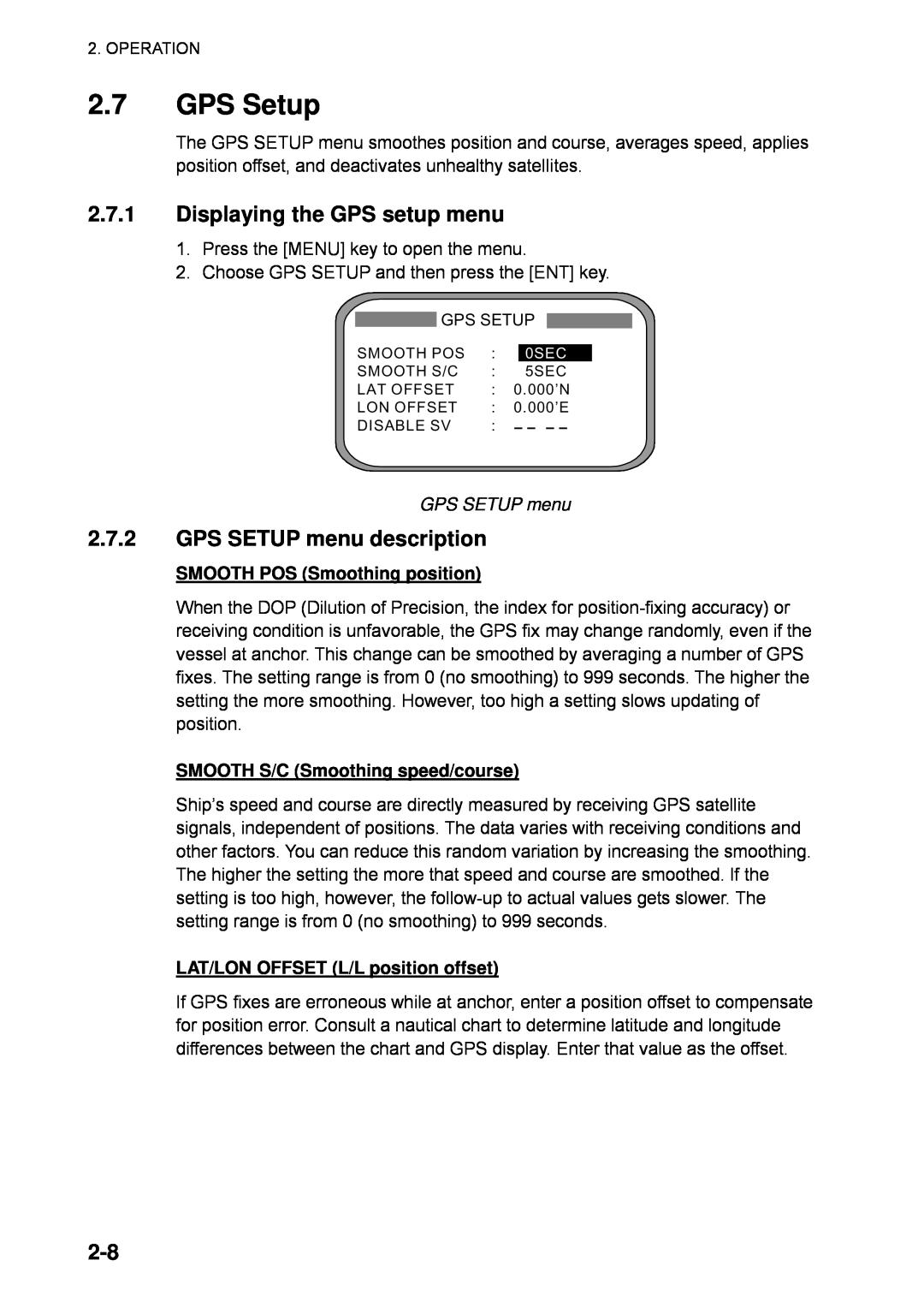
2.7GPS Setup
2.7.1Displaying the GPS setup menu
2.7.2GPS SETUP menu description
GPS SETUP menu
DISABLE SV Disable satellite
OUTPUT DATA SETUP menu
2.8Output Data
2.8.1Heading
2-10
4800BPS
9600BPS 19200BPS 38400BPS
DATA OUT1 menu, sentences
2-11
HE HN HC
25ms
100ms 200ms 1S 2S
2-12
Output sentence limitation
Sentence and maximum number of characters
400p/nm
2.8.2Log pulse
2-13
Log pulse options
2.9System Setup
SYSTEM SETUP
SYSTEM SETUP menu
2.9.1Geodetic data
2.9.3Using local time
2.9.2Units of measurement
2.9.4Time format
2-15
2.9.5Demonstration mode
2-16
2.10WAAS/DGPS Setup
2-17
WAAS DGPS AUTO
AUTO
2-18
Provider
GEO Satellite
Longitude
2-19
3FREQ is selected press the ENT key
5Set other digits appropriately
8.Press the DISP key to close the menu
2.11OTHERS Menu
2-20
AUTO
Others menu
2.12TRIP Menu
2-21
TRIP menu
2.13Resetting Distance Run
2.14Choosing External Heading Source for Backup
RESET DISTANCE prompt
Heading setup menu
3MAINTENANCE, TROUBLESHOOTING
3.1Preventive Maintenance
3.2Troubleshooting
Troubleshooting
Symptom
Cause
3.3Diagnostics
Diagnostic test1
TEST2 TEST3
Test menu options
Diagnostic test sequence
LCD CHECK
PUSH KEY
STOP PWR OFF
Diagnostic test2
TEST1
TEST2 TEST3
TEST START?
Diagnostic test3
ALARM options
TEST3 menu
TEST1
3.4Program Number
3.5Clearing Data
Program version no. display
Prompts for erasure of data
3.6Replacement of Battery
Battery Location
Prompt for exchanging battery
Prompt for turning off the power
3.7Replacement of Fuse
3.8Error Messages
Error Message
Message display
Error messages con’t from previous page
3-10
Error Message
Meaning
APPENDIX
1. Menu Tree
AP-1
2. Digital Interface
Output sentences of channel
Transmission interval
Load requirement as listener
Schematic diagrams
AP-3
J92120P8178FL35220R13
Data IN
Data sentences
AP-4
PFECatt- True heading, pitching, rolling
GGA - Global positioning system GPS fix data
AP-5
GNS - GNNS fix data
HDM- Heading - magnetic
HDT - Heading - true
AP-6
VBW - Dual ground/water speed
VDR - Set and drift
VHW - Water speed and heading
AP-7
VLW - Distance travelled through the water
VTG - Course over ground and ground speed
ZDA - Time and date
Signal
3. Input/Output Ports
AP-8
Port
AP-9
Signal
Port
Terminal Name
4. Parts List and Parts Location
ELECTRICAL PARTS LIST
F U R U N O
AP-10
AP-11
Display Unit, cover opened
ELECTRICAL PARTS LIST
SYMBOL TYPE
5. Geodetic Chart Codes
AP-12
6. Principle of Satellite Compass
AP-13
7. What is WAAS?
AP-14
EGNOS
MSAS
PACKING
LIST
INSTALLATION MATERIALS
SC-1203F
Page
工事材料表
SC-502-J/E
PACKING
LIST
ユニット
工事材料表
20AY-X-9404
20AY-X-9404
SC-1101-J/E
PACKING
LIST
ユニット
INSTALLATION MATERIALS
工事材料表
20AY-X-9401
20AY-X-9401
SPARE PARTS LIST FOR
U S E
NAME OF
OUTLINE
工事材料表
20AT-X-9411
OP20-31
20AT-X-9411
フラッシュマウントキット
A-10
A-11
フラッシュマウントキット
20AY-X-9403
OP20-17
Y. Hatai
Page
Page
Page
Page
Y. Hatai
INDEX
IN-1