Satellite Compass
Safety Instructions
Table of Contents
Iii
MAINTENANCE, Troubleshooting
Foreword
Features
Word to the Owner of the SC-50
System configuration
System Configuration
Standard supply
Equipment List
Optional equipment
Name Type Code No Qty Remarks
Principle of Operation
This page intentionally left blank
Mounting Considerations
Installation
Antenna unit
Horizontal separation between antenna and masts
Mast diameter Separation distance minimum
Antenna and field of view
Display unit, processor unit
Example of antenna installed below superstructures
Mounting dimensions for antenna, orienting the antenna
Installing the Antenna Units
Antenna unit SC-303
How to fasten the antenna cable
Waterproofing the antenna connector
Coating bolt, nut and washers with silicone sealant
Cable from antenna No. marked on cable
Antenna unit
How to insert the cable cover
Antenna unit SC-603
How to orient the antenna elements
Mounting
Antenna unit SC-603
Fixing antenna unit to pedestal
Orienting the antenna unit
Orient the antenna unit as shown in the illustration below
Welding the antenna unit
Antenna element
Fastening the antenna cable
Deck, bulkhead mount
Installing the Processor Unit
Processor unit orientation, deck mounting
Installation of processor unit on the underside of a desk
Installation on the underside of a desk
Desktop, overhead mounting
Installing the Display Unit
Flush mount
Flush mount F
Flush mount S kit Type OP20-17, Code No
Flush mount S
Flush mount S
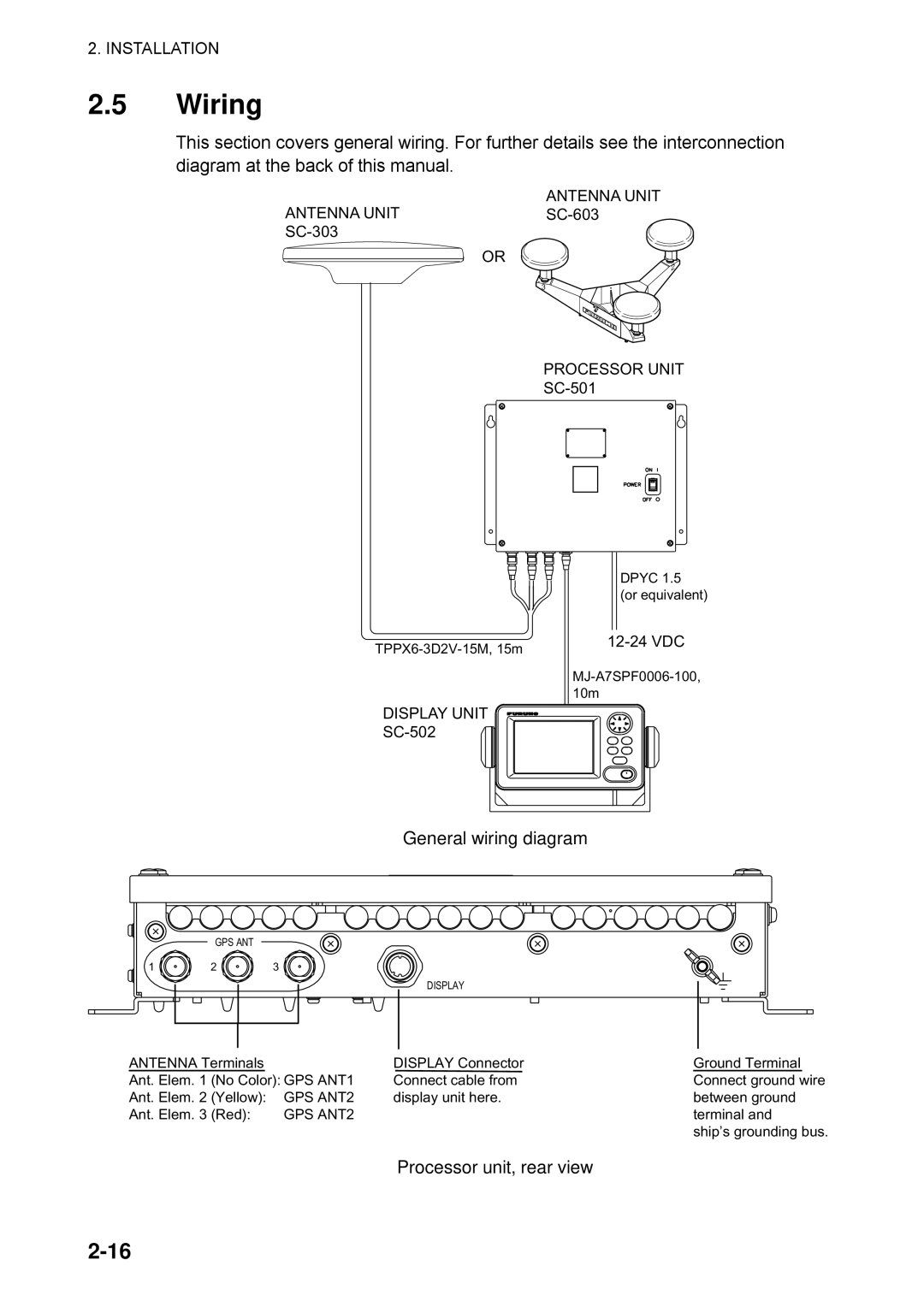
General wiring diagram
Wiring
Processor unit, rear view
Sectional view of coaxial cable 3D2V
How to install the optional antenna cable set
How to attach connector N-P-8DFB
How to attach connector N-P-8DFB
Installation setup menu
Initial Settings
Confirming satellite status choosing mounting method
Main menu
Choosing heading source
Heading setup menu
Satellite tracking status display
Connection of External Equipment
General wiring
Processor unit, cover opened
Cable Sectional view, fabrication
Fabrication of cables
Controls
Operation
Display unit
Panel Illumination, Display Contrast
Turning the Power On/Off
Processor unit
Description of displays
Choosing a Display
Heading display
Nav data display
Compass display
Steering display
ROT Rate-of-Turn display
Set and drift display, speed and distance run display
Set and Drift display, Distance Run display
Alarm menu
Dgps Alarm Setup
Dgps alarm options
Buzzer options
Satellite status display
Confirming Satellite Status
Displaying the GPS setup menu
GPS Setup
GPS Setup menu description
Output Data
Disable SV Disable satellite
Heading
Baud rate options
Data OUT1 menu, sentences
IEC, Nmea version options
Tx interval options
Heading talker options
Log pulse options
Log pulse
System Setup menu
System Setup
Geodetic data
Units of measurement
Using local time
Time format
Demonstration mode
Position fix mode options
WAAS/DGPS Setup
WAAS/DGPS menu
Waas Search options
GEO satellite and coverage area
Provider GEO Satellite Longitude
AUTO/MANUAL options
Operation
Others Menu
HDG Backup options
Others menu
HDG Restoration options
Trip menu
Trip Menu
Reset Distance prompt
Resetting Distance Run
This page intentionally left blank
Preventive Maintenance
MAINTENANCE, Troubleshooting
Troubleshooting
Troubleshooting
Symptom Cause Remedy
Diagnostic test1
Diagnostics
Test menu options
Test start prompt
Push KEY
Diagnostic test sequence
TEST2 display
Diagnostic test2
Alarm options
Diagnostic test3
Clearing Data
Program Number
Program version no. display
Prompts for erasure of data
Battery Location Type Code No
Replacement of Battery
Prompt for exchanging battery
Prompt for turning off the power
Error Messages
Replacement of Fuse
Error Message Meaning Remedy
Message display
Data ERR
Error messages con’t from previous
Menu Tree
Appendix
AP-1
AP-2
SC-50
Specifications
Furuno
IN-1
Index
Packing List
SC-501-J/E
SC-303
工事材料表
Installation Materials
フラッシュマウントキット
20AY-X-9403
SC-50/55/60
20AT-X-9410
Page
Page
Page