2. INSTALLATION
4.Choose INT or EXT as appropriate. Normally choose INT. If own GPS sensor is not working and a heading sensor such as a gyrocompass is available, choose EXT.
5.Press the [ENT] key.
6.Press the [DISP] key to close the menu.
2.7Connection of External Equipment
2.7.1General wiring
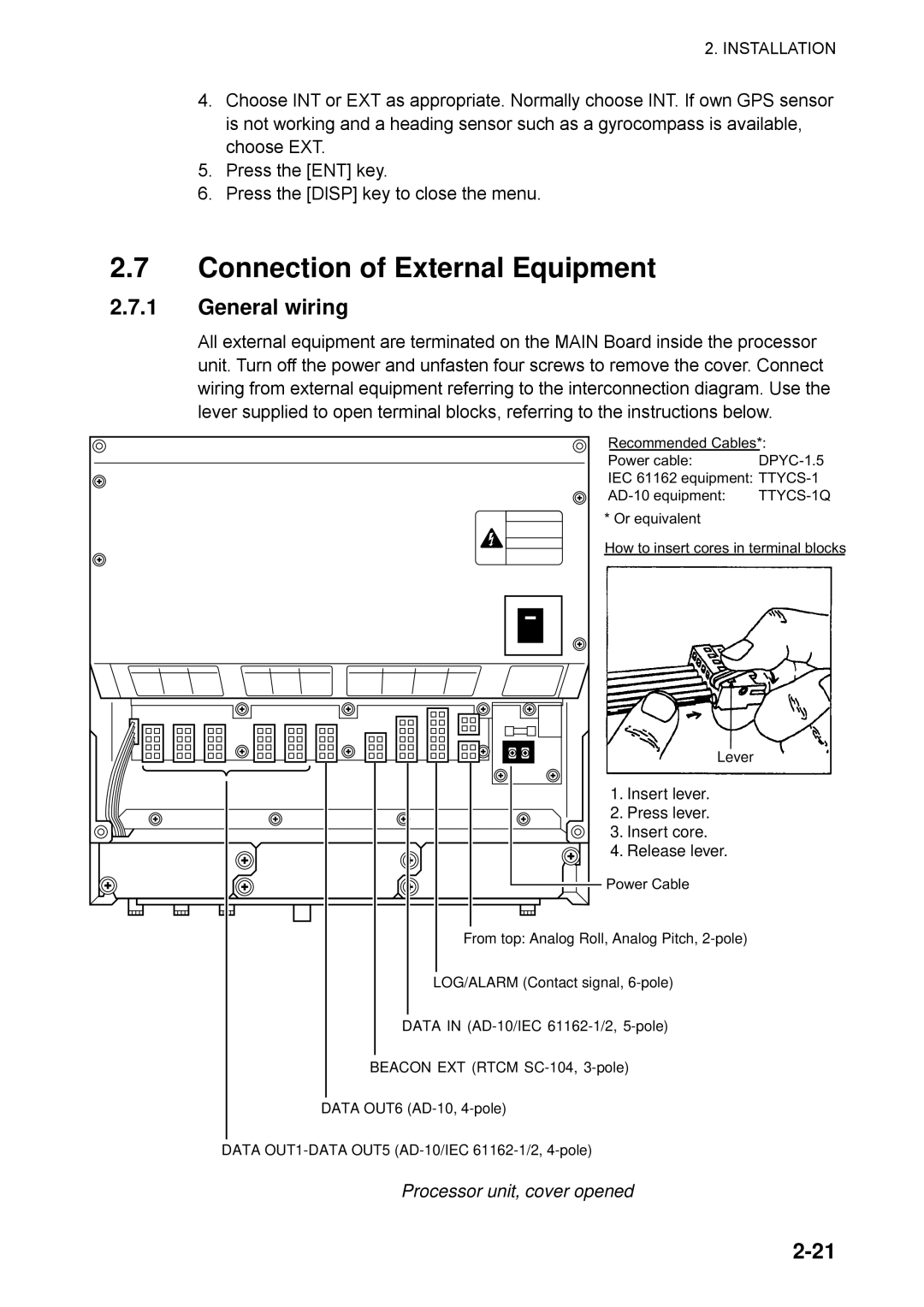
All external equipment are terminated on the MAIN Board inside the processor unit. Turn off the power and unfasten four screws to remove the cover. Connect wiring from external equipment referring to the interconnection diagram. Use the lever supplied to open terminal blocks, referring to the instructions below.
Recommended Cables*:
Power cable:DPYC-1.5
IEC 61162 equipment:
* Or equivalent
How to insert cores in terminal blocks
Lever
1. Insert lever.
2. Press lever.
3. Insert core.
4. Release lever.
Power Cable
From top: Analog Roll, Analog Pitch,
LOG/ALARM (Contact signal,
DATA IN
BEACON EXT (RTCM
DATA OUT6
DATA