1 PRINCIPLE OF OPERATION
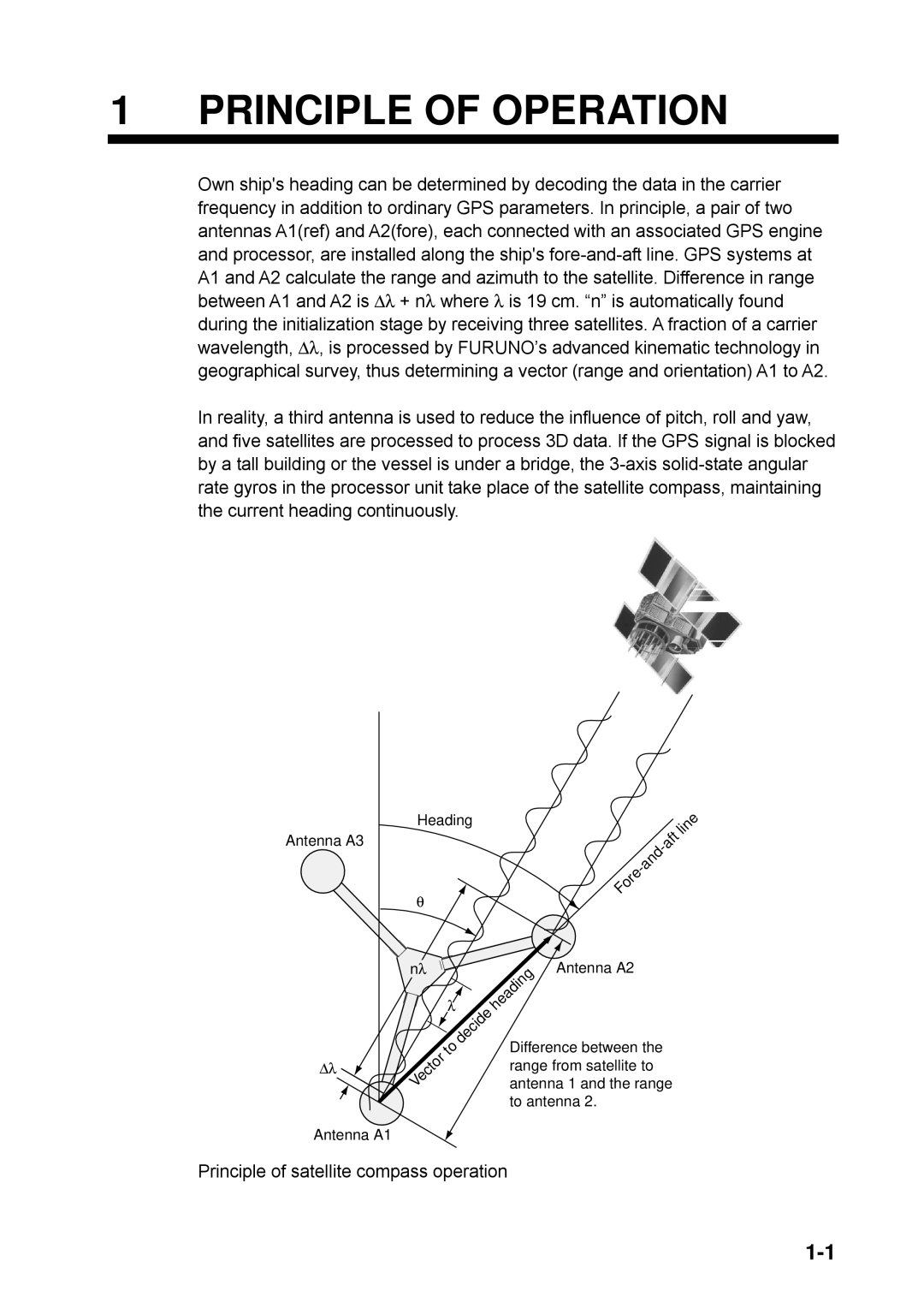
Own ship's heading can be determined by decoding the data in the carrier frequency in addition to ordinary GPS parameters. In principle, a pair of two antennas A1(ref) and A2(fore), each connected with an associated GPS engine and processor, are installed along the ship's
In reality, a third antenna is used to reduce the influence of pitch, roll and yaw, and five satellites are processed to process 3D data. If the GPS signal is blocked by a tall building or the vessel is under a bridge, the
Antenna A3
Heading |
| line |
| ||
|
| |
|
| |
θ | Fore |
|
|
|
∆λ
nλ
λ
Vector | to |
|
decide
heading | Antenna A2 |
|
Difference between the range from satellite to antenna 1 and the range to antenna 2.
Antenna A1
Principle of satellite compass operation