www . GarrettCom . com
Models 1008, 1016 and
Installation and User Guide
Magnum Workgroup Hubs “Ten Series”
Installation and User Guide 04/02
Workgroup Hubs Installation and User Guide
Magnum 1008, 1016 and
and optional 48VDC, 24VDC &125VDC-powered models
Fax 510
GarrettCom, Inc
47823 Westinghouse Drive Fremont, CA
Phone 510
TABLE OF CONTENTS
APPENDIX B OPTIONAL 48V POWER SUPPLY, ADDENDUM
Page
Revisions
Personal Hubs, 10Mb series
Personal Switches, 10/100Mb
The Magnum Line
Stackable Hubs, SNMP Optional
Network Standards
1.0 SPECIFICATIONS 1.1 Technical Specifications Performance
Connectors
Switches
1.2 Specifications - Repeater Port Modules RPMs
Power Supply Internal
For 48VDC power input option, see Appendix B Agency Approvals
Warranty
Magnum Magnum Magnum
Magnum 1000 Workgroup Hubs
1.4 Ordering Information
2.2 Product Description - Magnum 1000-series Workgroup Hubs
2.0 INTRODUCTION 2.1 Inspecting the Package and Product
Figure 2.2.1a Front view - Magnum 1008 Workgroup Hub
2.2.1 Magnum 1008 Workgroup Hub
115 - 230 VAC
Installation and User Guide 04/02
AC Power
Magnum 1000 Workgroup Hubs
Figure 2.2.2c Rear view - Magnum 1016 and 1024 Workgroup Hubs
Configurable Bonus Port
Figure 2.2.2b Front view - Magnum 1024 Workgroup Hub
RPM-FST Shown
PM Ribbon cable with 16 pin headers
Basic AUI port
Optional PM card
BPM shown
Figure 2.4a Magnum RPM Cards RPM-BNC, RPM-AUI
Magnum 1000 Workgroup Hubs Installation and User Guide 04/02
2.4 Bonus Port Configuration Options - RPMs and BPMs
Bonus port for optional Basic AUI port PM card BPM shown
Approx. 2 inches 5.1 cm
Figure 2.4c Physical Dimensions of Magnum Port Modules
Approx. 3 inches 7.6 cm
Approx
2.4.2 RPM-AUI
2.4.1 RPM-BNC
2.4.3 RPM-DTE
JUMPER ACROSS
RPM-FST Fiber ST, Twist-lock Connector
Connector
2.4.4
Magnum RPM-SMF
2.4.6 RPM-SMF Single-mode Fiber
not used
Magnum RPM-TP
2.4.7 RPM-TP Twisted Pair
Magnum BPM-AUI
2.4.8 BPM-BNC
Magnum BPM-BNC
2.4.9 BPM-AUI
Magnum BPM-FST
2.4.10 BPM-FST
2.4.11 BPM-TP
2.4.12 Special Option -- Second Bonus Port Models 1016 and
Workgroup connectivity into a larger network
2.5 Features and Benefits Low cost, stand-alone 10BASE-T connectivity
LEDs Simplify Network Installation and Maintenance
Internal Universal Power Supply with Auto-ranging
BNC Segment RPM-BNC Server 1024
Figure 2.6a Magnum 1000 Workgroup Hub in stand-alone configuration
Magnum 1000 Workgroup Hub
2.6 Applications
Fiber BPM
1016
1008
1024
Rack-mount Brackets 3.2 Powering the Magnum 1000 Workgroup Hub
3.0 INSTALLATION
installation requires a
installed in any standard 19 inch rack
IEEE Standard
3.3.1 Connecting Twisted Pair RJ-45, Unshielded or Shielded
3.3 Ethernet Media Connections
Media
3.3.2 Connecting ThickNet 10BASE5 AUI
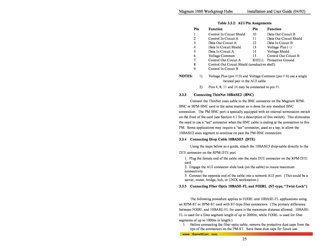
Table 3.3.2 AUI Pin Assignments
3.3.3 Connecting ThinNet 10BASE2 BNC
3.3.4 Connecting Drop Cable 10BASE5 DTE
3.3.5 Connecting Fiber Optic 10BASE-FL and FOIRL ST-type, “Twist-Lock
associated ports at each end of the fiber optic segment
3.3.6 Connecting Fiber Optic SMA-type, Screw-on
3.3.7 Connecting Single-Mode Fiber Optic SMF
at regular intervals you must use the color-coded strand on the
3.3.9 Rack-mounting
OPB Optical Power Budget = PTmin - PRmin
Rack-mounting purpose. The
brackets are more popular in
TELCO Industry and
consider as a standard for
Collisions When carrier is detected simultaneously on multiple ports, a jam pattern is generated on each port to create a collision condition. When a collision signal from one port is detected, it generates a jam pattern to the other ports
Packet Forwarded
4.2 Magnum 1000’s with BPM Local Bridge Functionality
Figure 4.2b Internal Packet Filtered
Table 4.2 BPM Functionality
Maintenance
Figure 4.2c External Packet
Forwarded
Figure 4.2e Local Segment Isolation with a Bridge Port Module BPM
4.3 Power Requirements
5.1 Before Calling for Assistance
5.0 TROUBLESHOOTING
5.3 Return Material Authorization RMA Procedure
5.2 When Calling for Assistance
5.4 Shipping and Packaging Information
APPENDIX A WARRANTY INFORMATION
No Problem Found
GarrettCom, Inc 213 Hammond Ave Fremont, CA Attn. Customer Service
Power Supply Internal 24 VDC Option
APPENDIX B Internal DC Power Supply Option
B1.0 SPECIFICATIONS - FOR MAGNUM 1000 WORKGROUP HUBS
Power Supply Internal -48 VDC Option
Block on Magnum 1000’s-48VDC
B4.0 INSTALLATION
B3.0 APPLICATIONS
Figure B4.1 -48VDC Terminal
B5.0 OPERATION
B7.0 TROUBLESHOOTING
The GND can be hooked at the last
B4.1 UL Requirements