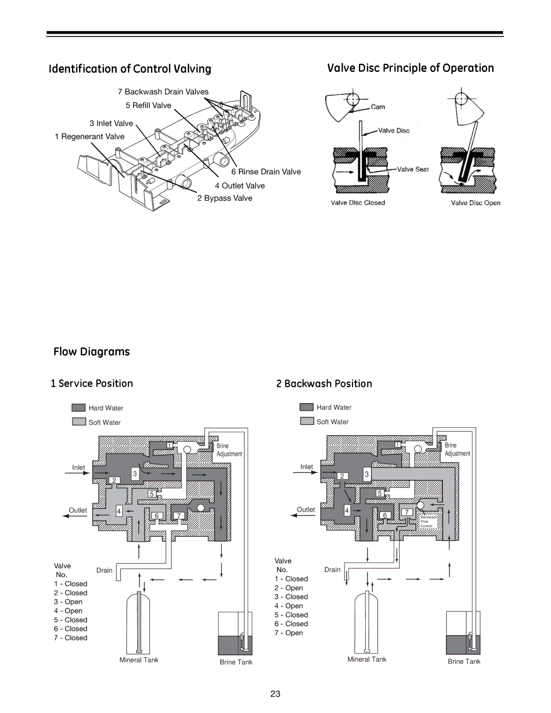
Identification of Control Valving | Valve Disc Principle of Operation |
|
|
|
|
7 Backwash Drain Valves |
5 Refill Valve |
3 Inlet Valve
1 Regenerant Valve
6 Rinse Drain Valve
4 Outlet Valve
2 Bypass Valve
Flow Diagrams
1 Service Position
![]()
![]() Hard Water
Hard Water
![]()
![]() Soft Water
Soft Water
1
Inlet
3
2
5
2 Backwash Position
![]()
![]() Hard Water
Hard Water
![]()
![]() Soft Water
Soft Water
Brine
Adjustment
Inlet
2 | 3 |
5
1
Brine Adjustment
Outlet
Valve
4 ![]()
![]()
6
7
Outlet
Valve
4 ![]()
![]()
6
7
Backwash
Flow
Control
No.
Drain
No. Drain
1 - Closed
1 - Closed
2 - Closed
3 - Open
4 - Open
5 - Closed
6 - Closed
7 - Closed
2 - Open
3 - Closed
4 - Open
5 - Closed
6 - Closed
7 - Open
Mineral Tank | Brine Tank | Mineral Tank | Brine Tank |
|
|
23