(continued)
●All ranges can tip.
●Injmy codd resdt.
●h~ the
●See the Instigation
Instmctions. | I |
ST~~ITY DEWCE~STALLATION~STRUC~ONS FORBRAC~T HT NO. 34M73
Tools needed:
●Phillips head screwdriver
●13/8”open end or adjustable wrench
The bracket attaches to floor or wall to hold either the right or left rear leg leveler. If fastening to the floor, be sure that the screws do not penetrate electrical wiring or plumbing. If this cannot be determined, use shorter screws that will not penetrate through flooring.
If the bracket came with your range, it is shipped attached to the lower range back. Remove and discard the shipping screw that holds the bracket and then follow the instructions below.
1.Decide whether the bracket will be installed on the right or left side of the range location.
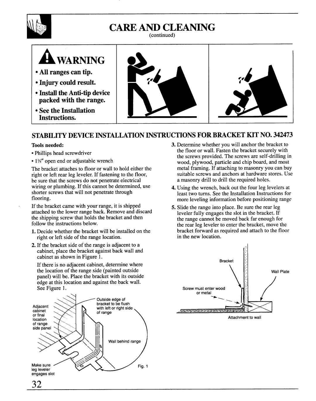
2.If the bracket side of the range is adjacent to a cabinet, place the bracket against back wall and cabinet as shown in Figure 1.
If there is no adjacent cabinet, determine where the location of the range side (painted outside panel) will be. Place the bracket with its outside edge at this location and against the back wall. See Figure 1.
| Outside edge of | |
Adjacent | bracket to be flush | |
with left orrightside | ||
cabinet | ofrange | |
orfinal | ||
| ||
location |
| |
ofrange |
| |
side panel |
|
3.Determine whether you will anchor the bracket to the floor or wall. Fasten the bracket securely with the screws provided. The screws are
4.Using the wrench, back out the four leg levelers at least two turns. See the Installation Instructions for more leveling information before positioning range
5.Slide the range into place. Be sure the rear leg leveler fully engages the slot in the bracket. If the range cannot be moved back far enough for the rear leg leveler to enter the bracket, move the bracket forward as required and attach to the floor in the new location.
.’.
,:.
;.
Bracket | :: |
|
| .:: | |
| >. | |
| ,,. | wall Plate |
| $,, |
|
| x, |
|
Screw must enter wood \/~ | .’\ |
|
> |
| |
,, |
| |
or metal | .,\ | / |
,, |
,. | ||
\.:. | ||
| ||
| Attachment to wall |
~ | K | , |
|
| \\ |
| Wall behind range |
| d | ~ |
|
| \@ |
|
|
| @. |
|
|
Make sure | /’& | \ | Rg. 1 |
leg leveler |
|
|
|
engages slot
32